Minimally invasive puncture sampling device for pathological examination
A sampling device and pathological technology, applied in the field of pathological diagnosis, can solve the problems of bending damage, lack of effective protection of the needle core, affecting the process of minimally invasive surgery, etc., to achieve the effect of avoiding damage and simple operation
- Summary
- Abstract
- Description
- Claims
- Application Information
AI Technical Summary
Problems solved by technology
Method used
Image

Examples
Embodiment Construction
[0029] In order to make the object, technical solution and advantages of the present invention clearer, the present invention will be described in further detail below in conjunction with the accompanying drawings and embodiments. It should be understood that the specific embodiments described here are only used to explain the present invention, not to limit the present invention.
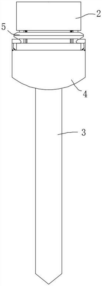
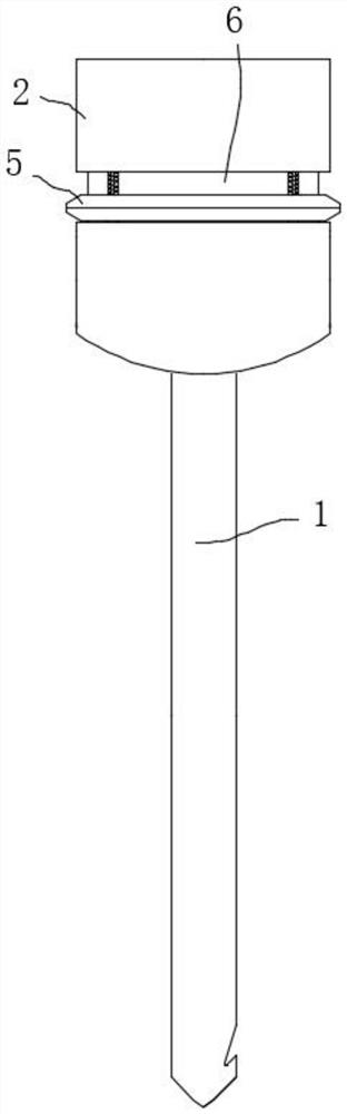
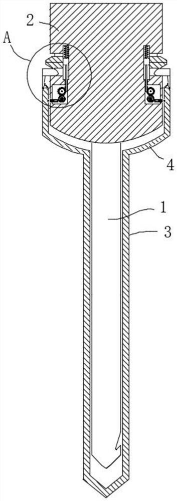
[0030] Please combine Figure 1 to Figure 8 A minimally invasive puncture sampling device for pathological examination, comprising a needle core 1 for puncture sampling the minimally invasive site, a hand-held block 2 arranged on the needle core 1, a protective sheath assembly and a release assembly. In this embodiment, one end of the needle core 1 is the tip, and an oblique groove (not marked) is opened on the side wall of the needle core 1 near the tip, through which the tissue block in the minimally invasive area is conveniently removed.
[0031] The protective sheath assembly includes a needle...
PUM
 Abstract
Description
Claims
Application Information
 - Generate Ideas
- Intellectual Property
- Life Sciences
- Materials
- Tech Scout
- Unparalleled Data Quality
- Higher Quality Content
- 60% Fewer Hallucinations
Browse by: Latest US Patents, China's latest patents, Technical Efficacy Thesaurus, Application Domain, Technology Topic, Popular Technical Reports.
© 2025 PatSnap. All rights reserved.Legal|Privacy policy|Modern Slavery Act Transparency Statement|Sitemap|About US| Contact US: help@patsnap.com