New energy automobile power flexible transmission system
A new energy vehicle, flexible transmission technology, applied in power units, electric power units, vehicle components, etc., can solve the problems of reducing the comfort, vibration, and stability of new energy vehicles, and achieve reduced frustration, The effect of improving comfort and increasing toughness
- Summary
- Abstract
- Description
- Claims
- Application Information
AI Technical Summary
Problems solved by technology
Method used
Image


Examples
Embodiment 1
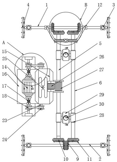
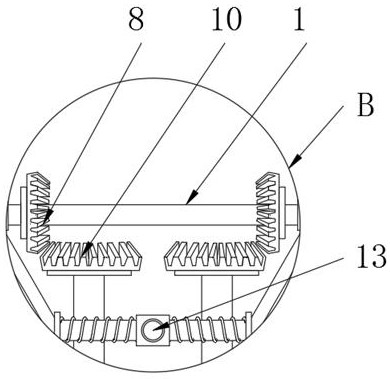
[0027] Refer to the attached Figure 1-5 , a new energy vehicle power flexible transmission system, including a front drive shaft 1, a rear drive shaft 2, a main transmission shaft 5, a driven transmission shaft 6, a bidirectional motor 14, a gearbox 15 and a barometer 30, the main transmission shaft 5 and the slave The drive transmission shaft 6 is located between the front drive shaft 1 and the rear drive shaft 2, the gearbox 15 is located on one side of the main transmission shaft 5, the bidirectional motor 14 is located on one side of the gearbox 15, and the barometer 30 is located between the main transmission shaft 5 and the driven shaft. Between the transmission shafts 6, two front drive worm gears 8 are fixed on one side outer wall of the front drive shaft 1, two driving gears 10 are fixed on one side outer wall of the rear drive shaft 2, and two ends of the main drive shaft 5 are fixedly provided with Drive gear 10, the two ends of driven transmission shaft 6 are fixe...
Embodiment 2
[0029] Refer to the attached Figure 1-2 and 4, on the basis of Embodiment 1, the output shafts at both ends of the bidirectional motor 14 are fixedly provided with a spring tube coupling 17, and one end of the two spring tube couplings 17 is fixedly provided with a driving pulley 18, which is connected by a spring tube The shaft device 17 drives the driving pulley 18 to rotate, which can reduce the instantaneous kinetic energy during the rotation of the two-way motor 14 and reduce the sense of frustration during the driving of the new energy vehicle. The outer wall of the two driving pulleys 18 is provided with a positioning column 22, and the two-way motor The outer wall of the bottom of 14 is fixedly provided with a fixed base 16, and the two ends of the fixed base 16 are fixedly provided with a vertically upward positioning block 19, and one side of the two positioning blocks 19 is provided with a bearing 20, and the inner wall of the bearing 20 is flexibly connected. Posi...
Embodiment 3
[0031] Refer to the attached Figure 1-2, on the basis of Embodiment 1, the gearbox 15 includes a gearbox input shaft 23, the two ends of the gearbox input shaft 23 are fixedly provided with driven pulleys 24, the outer walls of the two driven pulleys 24 and the two driving pulleys 18 The outer wall is socketed with a belt strip, the top outer wall of the gearbox 15 is provided with a shift lever 25, and the driven pulley 24 is driven to rotate by the belt strips socketed on the outer wall of the two driving pulleys 18, which further improves the stabilizing effect of the two-way motor 14 output , one side outer wall of the main drive rotating shaft 5 is fixedly provided with a drive gear 27, and the output shaft of the gearbox 15 is fixedly provided with a gearbox output gear 26, and the drive gear 27 meshes with the gearbox output gear 26, and the gearbox output gear 26 can drive The driving gear 27 rotates, and the driving gear 27 can drive the main transmission rotating sh...
PUM
 Abstract
Description
Claims
Application Information
 - Generate Ideas
- Intellectual Property
- Life Sciences
- Materials
- Tech Scout
- Unparalleled Data Quality
- Higher Quality Content
- 60% Fewer Hallucinations
Browse by: Latest US Patents, China's latest patents, Technical Efficacy Thesaurus, Application Domain, Technology Topic, Popular Technical Reports.
© 2025 PatSnap. All rights reserved.Legal|Privacy policy|Modern Slavery Act Transparency Statement|Sitemap|About US| Contact US: help@patsnap.com