Supercharge Your Innovation With Domain-Expert AI Agents!

Ultra-long distance distributed optical fiber vibration sensing detection method and device

A distributed optical fiber and vibration sensing technology, applied in measurement devices, measuring ultrasonic/sonic/infrasonic waves, instruments, etc., can solve the problems of signal weakening, weak back Rayleigh scattering signal strength, detection by sensing system, etc. The effect of extending the sensing distance

Pending Publication Date: 2022-05-24
SOUTHERN MARINE SCI & ENG GUANGDONG LAB (ZHUHAI) +1
View PDF8 Cites 0 Cited by
  • Summary
  • Abstract
  • Description
  • Claims
  • Application Information

AI Technical Summary

Problems solved by technology

However, in long-distance optical communication, the back Rayleigh scattering signal intensity generated when light is transmitted in the optical fiber is weak, so the detection distance is generally less than 40km
Even if the external disturbance to the optical fiber is very strong, when the distance between the disturbance source and the distributed sensing system exceeds 40km, the back Rayleigh scattering signal will be attenuated when transmitted in the optical fiber, which will cause the signal to be greatly weakened, or even unable to be transmitted. Therefore, the detection distance of the current distributed sensing system has certain limitations.

Method used


Image

  • Ultra-long distance distributed optical fiber vibration sensing detection method and device
  • Ultra-long distance distributed optical fiber vibration sensing detection method and device
  • Ultra-long distance distributed optical fiber vibration sensing detection method and device

Examples


Embodiment 1

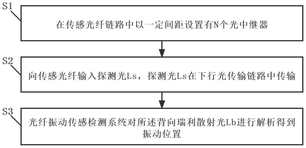
[0032] This embodiment proposes an ultra-long-distance distributed optical fiber vibration sensing detection method, such as figure 1 As shown, it is a flowchart of the ultra-long-distance distributed optical fiber vibration sensing detection method of this embodiment.

[0033] The ultra-long-distance distributed optical fiber vibration sensing detection method proposed in this embodiment includes the following steps:

[0034] S1. N optical repeaters 1 are arranged at a certain interval in the sensing fiber link.

[0035] In this embodiment, the spacing between adjacent optical repeaters 1 is determined by the attenuation coefficient of the sensing fiber link segment between them and the amplification gain coefficient of the next-stage optical repeater 1 .

[0036] S2. Input the detection light Ls to the sensing fiber, and the detection light Ls is transmitted in the downlink optical transmission link.

[0037] The probe light Ls input in this step is transmitted in the sens...

Embodiment 2

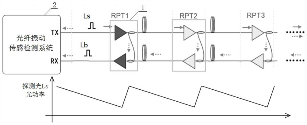
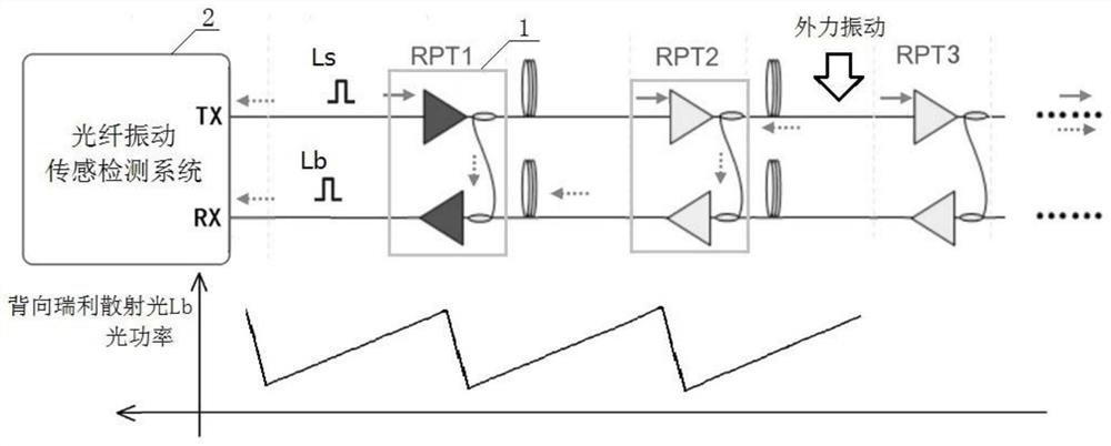
[0047] This embodiment proposes an ultra-long-distance distributed optical fiber vibration sensing detection device, and the ultra-long-distance distributed optical fiber vibration sensing detection method proposed in Embodiment 1 is applied. like Figure 4 As shown, it is a schematic structural diagram of the ultra-long-distance distributed optical fiber vibration sensing detection device of this embodiment.

[0048] The ultra-long-distance distributed optical fiber vibration sensing detection device proposed in this embodiment includes N optical repeaters 1 and an optical fiber vibration sensing detection system 2 .

[0049] Among them, N optical repeaters 1 are arranged in the sensing fiber link to be detected at a certain distance, and the distance between the adjacent optical repeaters 1 is determined by the attenuation of the sensing fiber link segment between them. The coefficient and the amplification gain coefficient of the next-stage optical repeater 1 are determine...

Embodiment 3

[0059] This embodiment makes improvements on the basis of the ultra-long-distance distributed optical fiber vibration sensing detection device proposed in the second embodiment.

[0060] The optical fiber vibration sensing detection system 2 in this embodiment includes a light source 201 , an optical beam splitter 202 , a circulator 203 , an optical combiner 204 and a detection module 3 .

[0061] like Image 6 As shown, it is a schematic structural diagram of the ultra-long-distance distributed optical fiber vibration sensing detection device of this embodiment.

[0062] Further, the light source 201 in this embodiment adopts a narrow linewidth light source, wherein the narrower the linewidth of the light source 201 used, the better the coherence of the light source 201 and the smaller the phase noise, which effectively improves the signal-to-noise ratio of long-distance detection. .

[0063] In addition, the wavelength of the narrow linewidth light source 201 in this embod...


PUM


Abstract

The invention relates to the technical field of optical fiber communication, and provides an ultra-long distance distributed optical fiber vibration sensing detection method and device, and the method comprises the following steps: arranging N optical repeaters in a sensing optical fiber link at a certain interval, the distance between the adjacent optical repeaters is determined by the attenuation coefficient of the sensing optical fiber link section between the two optical repeaters and the amplification gain coefficient of the next optical repeater; inputting detection light into the sensing optical fiber, wherein the detection light is transmitted in the downlink optical transmission link; when the sensing optical fiber is influenced by vibration, back Rayleigh scattering light generated by vibration is transmitted back to back in the uplink direction, and the back Rayleigh scattering light enters an uplink optical transmission link through a loopback link in the nearest optical repeater; the backward Rayleigh scattering light is subjected to optical power amplification through an amplifier of the optical repeater in the uplink optical transmission link and then returns to the optical fiber vibration sensing detection system, and the optical fiber vibration sensing detection system analyzes the backward Rayleigh scattering light to obtain a vibration position.

Description

technical field [0001] The present invention relates to the technical field of optical fiber communication, and more particularly, to an ultra-long-distance distributed optical fiber vibration sensing detection method and device. Background technique [0002] Distributed fiber optic vibration sensors include interferometric sensors and backscatter sensors. The formation of Rayleigh scattering in optical fibers mainly originates from the non-uniformity of material density and refractive index due to various reasons during the optical fiber fabrication process. The optical fiber distributed sensor based on interference technology is mainly based on the phase modulation characteristics of the external disturbance signal to the light wave transmission in the optical fiber, and realizes the sensing and detection of the external disturbance signal by demodulating the phase information change of the returned light wave signal. The traditional Optical Time-Domain Reflectometry (OTD...

Claims


Application Information

Patent Timeline
IPC IPC(8): G01H9/00
CPCG01H9/004
Inventor 陈少义隋琪朱坤李朝晖
Owner SOUTHERN MARINE SCI & ENG GUANGDONG LAB (ZHUHAI)
Features
  • R&D
  • Intellectual Property
  • Life Sciences
  • Materials
  • Tech Scout
  • Unparalleled Data Quality
  • Higher Quality Content
  • 60% Fewer Hallucinations
Learn More