Antenna connection detection method and related device
A connection detection and antenna technology, which is applied in the field of antenna connection detection, equipment and computer-readable storage media, and antenna connection detection devices, can solve the problems of easy changes in distance and relative angle, large test deviation, and high cost, and achieve saving Production space and equipment costs, accurate testing, and the effect of reducing testing costs
- Summary
- Abstract
- Description
- Claims
- Application Information
AI Technical Summary
Problems solved by technology
Method used
Image

Examples
Example Embodiment
[0053] Example 1
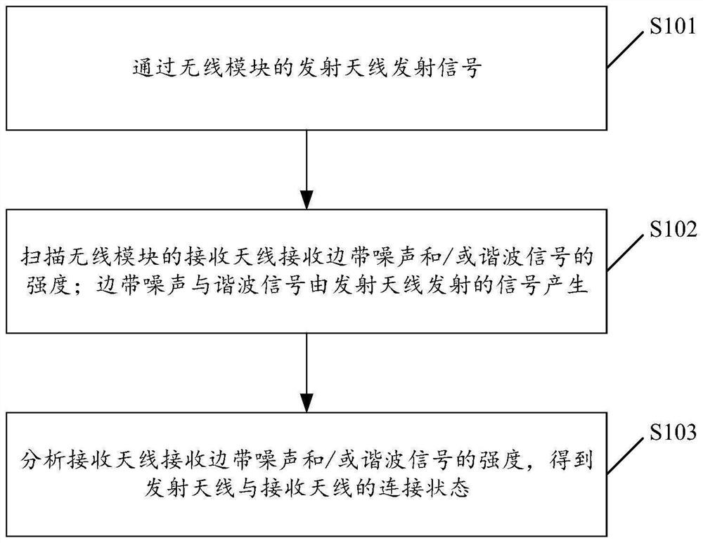
[0054] Please refer to figure 2 , figure 2 For a schematic flowchart of an antenna connection detection method provided by an embodiment of the present application, refer to figure 2 As shown, the method mainly includes:
[0055] S101: transmit a signal through the transmitting antenna of the wireless module;
[0056] S102: Scan the strength of the sideband noise and / or harmonic signal received by the receiving antenna of the wireless module; the sideband noise and the harmonic signal are generated by the signal transmitted by the transmitting antenna;
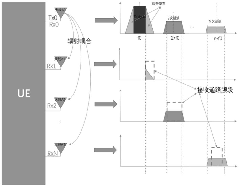
[0057] combine image 3 shown, the wireless module ( image 3 The signal transmitted by the transmitting antenna of the UE) shown in will generate higher interference noises such as sideband noise and harmonic signals after power amplification. The embodiment of the present application uses the sideband noise generated by the signal transmitted by the transmitting antenna of the wireless module. Rep...
Example Embodiment
[0079] Embodiment 2
[0080] On the basis of the above-mentioned embodiment, this embodiment further includes: before transmitting the signal through the transmitting antenna of the wireless module:
[0081] Scan the environmental noise floor of the receiving frequency band of the receiving antenna corresponding to the transmitting frequency band of the transmitting antenna;
[0082] Determine whether the ambient noise floor meets the preset conditions;
[0083] If it is satisfied, the signal located in the transmitting frequency band is transmitted through the transmitting antenna;
[0084] If not, adjust the transmit frequency band of the transmit antenna until the environmental noise floor of the receive frequency band of the receive antenna corresponding to the transmit frequency band of the transmit antenna satisfies the preset condition, and transmit the signal in the transmit frequency band through the transmit antenna.
[0085] In order to further improve the detecti...
Example Embodiment
[0118] On the basis of the above embodiment, as a specific implementation manner, the judgment module includes:
[0119] a judging unit for judging whether the environmental noise floor is not greater than the difference between the corresponding intensity threshold and a preset value;
[0120] A determining unit, configured to, if not greater than, the environmental noise floor satisfies the preset condition; if greater than, the environmental noise floor does not meet the preset condition.
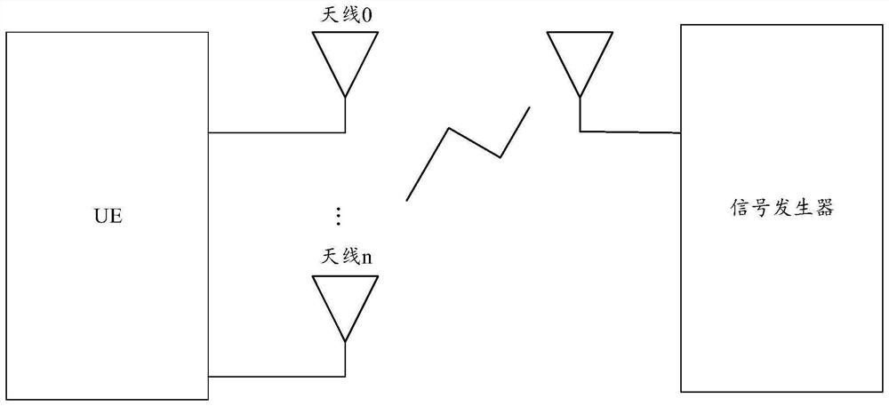
[0121] The antenna connection detection device provided in this application replaces the external signal generator with the sideband noise and harmonic signal generated by the signal emitted by the wireless module itself as the signal source, and removes the dependence on the external signal generator, thereby greatly reducing the dependence on the external signal generator. Reduced inspection costs. In addition, once the product is determined, the relative position (including distance,...
PUM
 Abstract
Description
Claims
Application Information
 - R&D Engineer
- R&D Manager
- IP Professional
- Industry Leading Data Capabilities
- Powerful AI technology
- Patent DNA Extraction
Browse by: Latest US Patents, China's latest patents, Technical Efficacy Thesaurus, Application Domain, Technology Topic.
© 2024 PatSnap. All rights reserved.Legal|Privacy policy|Modern Slavery Act Transparency Statement|Sitemap