Hermetically sealed compressor, refrigeration cycle device, and method for manufacturing hermetically sealed compressor

A manufacturing method, compressor technology, applied in the direction of machine/engine, mechanical equipment, liquid fuel engine, etc., can solve problems such as deviation

Pending Publication Date: 2022-06-24
MITSUBISHI ELECTRIC CORP
1 Cites 0 Cited by

AI-Extracted Technical Summary

Problems solved by technology

However, if the positional relationship between the protruding container and the cylinder deviates from the normal position, the positional relationshi...

Method used

In this way, before the spring guide 40 and the spring 36 are installed in the airtight container 10, the engagement of the protruding container 50 to the airtight container 10 can prevent the thermal deformation of the spring guide 40 and the spring 36, and make the protruding container Sealed within 50.
[0049] On the other hand, in the first embodiment, the spring guide 40 is separately provided in the protruding container 50, and the spring 36 is disposed on the spring guide 40. Also, the spring guide 40 is directly fixed to the cylinder 31 . That is, the spring 36 is provided on the basis of the cylinder 31 . Therefore, even if the central axis of the cylinder 31 is inclined relative to the central axis of the airtight container 10 at the time of manufacture, the spring 36 is not affected by the inclination, and it can rotate in a direction perpendicular to the central axis of the cylinder 31 . The precision is well set. Therefore, the positional accuracy of the spring 36 and the vane 35 can be ensured. Accordingly, it is possible to suppress twisting of the spring 36 during expansion and contraction of the spring 36 , and it is possible to stably operate the spring 36 .
[0065] Thus, by providing the ring 10e around the through hole 10d to which the protruding container 50 is joined, the contact distance between the one end 50a of the cylindrical portion 51 and the ring 10e can be ensured. Therefore, even if a joining method by brazing or welding is used, defects such as pinholes are less likely to occur, and good joining can be performed.
[0072] In the above manufacturing method, since the protruding container 50 is joined to the airtight container 10 at the initial stage, thermal deformation of the spring guide 40 and the spring 36 can be prevented. That is, when the spring guide 40 and the spring 36 are attached to the airtight container 10, when the step of joining the protruding container 50 and the airtight container 10 is performed, the heat at the time of joining may be transferred to the spring guide 40 and the spring 36. . However, in this Embodiment 1, by performing the process of joining the protruding container 50 and the airtight container 10 before attaching the spring guide 40 and the spring 36 to the airtight container 10, it is possible to prevent the spring guide 40 and the spring 36 from breaking. Thermal deformation.
[0078] The process of attaching the protruding container 50 to the airtight container 10 shown in FIG. 7 is the same as that in FIG. 6 . Moreover, since the cylindrical part 51 is divided into the front cylindrical part 51a and the rear cylindrical part...

Abstract

This hermetic compressor is provided with: a hermetic container; the hollow cylinder body is accommodated in the sealed container; a rotary piston that eccentrically rotates along the inner peripheral wall of the cylinder; a vane that reciprocates in a vane groove provided in the cylinder in the radial direction of the cylinder; and a spring that urges the vane toward the side where the rotary piston is disposed. The hermetic compressor is further provided with: a protruding container which is provided so as to protrude from the hermetic container in the radial direction of the cylinder on the opposite side from the cylinder, and which forms a hermetic space by having one end thereof joined to the hermetic container and communicating with the inside of the hermetic container; and a spring guide which is disposed in the sealed space of the protruding container and in which a spring is fixed. An insertion hole is formed in the outer peripheral wall of the cylinder, and one end of the spring guide is inserted into and fixed to the insertion hole of the cylinder.

Application Domain

Pump componentsRotary piston pumps +2

Technology Topic

PhysicsHollow cylinder +4

Image

  • Hermetically sealed compressor, refrigeration cycle device, and method for manufacturing hermetically sealed compressor
  • Hermetically sealed compressor, refrigeration cycle device, and method for manufacturing hermetically sealed compressor
  • Hermetically sealed compressor, refrigeration cycle device, and method for manufacturing hermetically sealed compressor

Examples

  • Experimental program(3)

Example Embodiment

[0020] Embodiment 1.
[0021] [hermetic compressor 100]
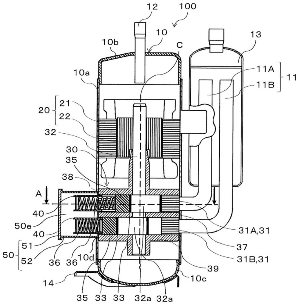
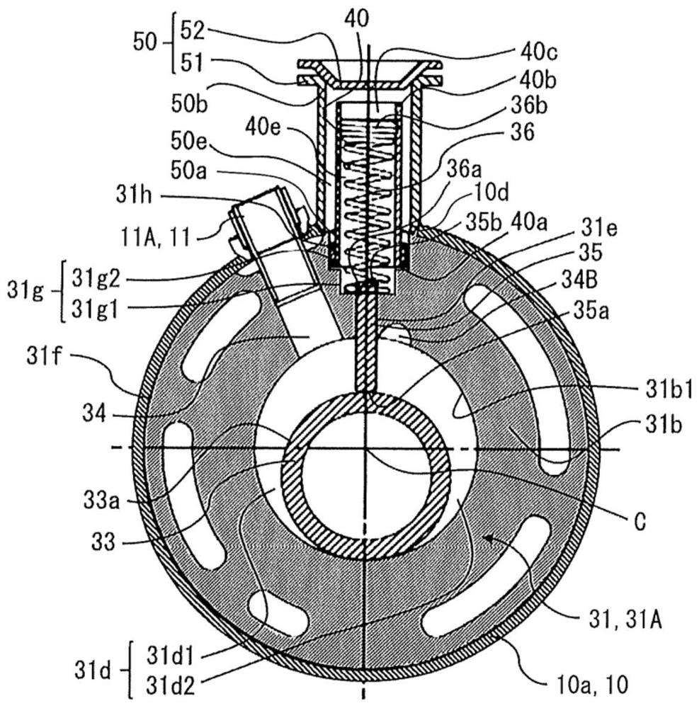
[0022] figure 1 It is a schematic vertical cross-sectional view of the hermetic compressor according to the first embodiment. figure 2 Yes figure 1 A-A line cross-sectional schematic diagram. in, figure 2 Indicates the state where the A-A line cross-section is rotated 90 degrees counterclockwise.
[0023] The hermetic compressor 100 is one of elements constituting a refrigeration cycle used in, for example, an air conditioner, a refrigerator, a refrigerator, a vending machine, a water heater, or the like. The hermetic compressor 100 is a double rotary compressor having two compression chambers. The hermetic compressor 100 includes a hermetic container 10 , a motor mechanism part 20 and a compression mechanism part 30 accommodated in the hermetic container 10 . Moreover, the hermetic compressor 100 has the accumulator 13 outside the hermetic container 10 , and has the suction pipe 11 connecting the hermetic container 10 and the accumulator 13 . In addition, the hermetic compressor 100 includes a protruding container 50 that accommodates a spring 36 that biases the vane 35 described later, and forms a closed space 50e that communicates with the hermetic container 10 .
[0024] (Airtight container 10)
[0025] The hermetic container 10 constitutes the outer casing of the hermetic compressor 100, and is composed of an iron member. The airtight container 10 includes a substantially cylindrical intermediate container 10a, an upper container 10b that closes an upper opening of the intermediate container 10a, and a lower container 10c that closes a lower opening of the intermediate container 10a. The airtight container 10 is fitted into the upper container 10b in the upper opening of the middle container 10a, and the lower container 10c is fitted in the lower opening of the middle container 10a to maintain a closed state. The airtight container 10 is arranged on the pedestal 14 , and the lower container 10 c is fixed to the pedestal 14 . In the hermetic compressor 100, the pedestal 14 is fixed to the installation place by bolts or the like.
[0026] The suction pipe 11 to which the accumulator 13 is attached is connected to the middle tank 10a. A discharge pipe 12 is connected to the upper container 10b. The suction pipe 11 is a connecting pipe for sending the low-temperature and low-pressure gas refrigerant sucked through the accumulators 1 to 3 into the compression mechanism part 30 . The discharge pipe 12 is a connecting pipe for discharging the high-temperature and high-pressure gas refrigerant in the airtight container 10 compressed by the compression mechanism unit 30 to the outside of the airtight container 10 .
[0027] (Electric Mechanism Section 20)
[0028] The motor mechanism unit 20 rotates the rotating shaft 32 inside the airtight container 10 . The electric mechanism part 20 is arranged above the compression mechanism part 30 in the airtight container 10 . The motor mechanism unit 20 includes a stator 21 fixed to the inner peripheral wall of the intermediate container 10 a , and a rotor 22 rotatably fitted to the inner peripheral side of the stator 21 . The stator 21 is fixed to the middle container 10a of the airtight container 10 by various fixing methods such as shrink fit or welding, for example. A rotating shaft 32 is fixed to the center portion of the rotor 22 . The rotating shaft 32 extends downward from the motor mechanism unit 20 . The stator 21 rotates the rotor 22 by electric power supplied from the outside of the hermetic compressor 100 .
[0029] (compression mechanism part 30 )
[0030] The compression mechanism unit 30 is housed in the airtight container 10 and compresses the refrigerant flowing into the airtight container 10 . The compression mechanism part 30 is arranged below the electric mechanism part 20, and is fixed to the middle container 10a. The compression mechanism unit 30 includes two compression mechanisms arranged in the axial direction of the rotating shaft 32 , an upper bearing 38 , a lower bearing 39 , and a partition plate 37 . Each compression mechanism includes a hollow cylinder 31 , a rotary piston 33 , a vane 35 , a spring 36 , and a cylindrical spring guide 40 in which the spring 36 is accommodated. Two spring guides 40 are arranged in the protruding container 50 . The protruding container 50 is provided in the airtight container 10 so as to protrude to the side opposite to the cylinder body 31 with respect to the airtight container 10 in the radial direction of the cylinder body 31 . Hereinafter, the cylinder block 31 of the compression mechanism on the upper side is referred to as an upper cylinder block 31A, and the cylinder block 31 of the compression mechanism on the lower side is referred to as a lower cylinder block 31B.
[0031] In the airtight container 10, the upper cylinder 31A is arranged above the lower cylinder 31B. On the upper part of the upper cylinder 31A, the upper bearing 38 is arranged so as to be in contact with the upper end surface of the upper cylinder 31A, and the upper end surface of the upper cylinder 31A is closed by the upper bearing 38 . In the lower part of the lower cylinder block 31B, the lower bearing 39 is arranged so as to be in contact with the lower end surface of the lower cylinder block 31B, and the lower end surface of the lower cylinder block 31B is closed by the lower bearing 39 . The partition plate 37 is arranged between the upper cylinder 31A and the lower cylinder 31B, and closes the lower end face of the upper cylinder 31A and the upper end face of the lower cylinder 31B.
[0032] as described later figure 2 As shown, suction holes 34 and discharge holes 34B are formed on both sides of the upper cylinder block 31A and the lower cylinder block 31B with the vane grooves 31e interposed therebetween in the circumferential direction, respectively. The suction pipe 11A is connected to the suction hole 34 of the upper cylinder 31A. The suction pipe 11B is connected to the suction hole 34 of the lower cylinder 31B. In addition, the above-mentioned suction pipe 11 is a general term for suction pipe 11A and suction pipe 11B. The discharge hole 34B is formed radially outward from the inner peripheral wall 31b of the cylinder block 31 , and communicates with the space in the airtight container 10 via a discharge hole (not shown) formed in the upper bearing 38 .
[0033] The rotary shaft 32 has an eccentric portion 32a that is eccentric in one radial direction on one end portion side in the axial direction. In addition, the other end portion side in the axial direction of the rotating shaft 32 is inserted into and fixed to the center portion of the rotor 22 of the motor mechanism portion 20 . The rotating shaft 32 is rotatably supported by the upper bearing 38 and the lower bearing 39 , and rotates together with the rotor 22 .
[0034]The spring guide 40 is provided so as to protrude from the airtight container 10 to the outside, and the spring 36 is accommodated and fixed inside. The spring guides 40 are provided corresponding to the upper cylinder 31A and the lower cylinder 31B, respectively, and are collectively accommodated in the protruding container 50 .
[0035] Below, use figure 2 as well as figure 1 , the structure of the compression mechanism part 30 will be further described. The relationship between the rotary piston 33, vane 35, spring 36, and spring guide 40 in the upper cylinder 31A is the same as the relationship between the rotary piston 33, vane 35, spring 36, and spring guide 40 in the lower cylinder 31B. Therefore, in the following description, the upper cylinder 31A and the lower cylinder 31B will not be described separately, and the cylinder 31 which is a general term of the upper cylinder 31A and the lower cylinder 31B will be used for description. In addition, in figure 2 In the figure, the illustration of the eccentric portion 32a arranged in the cylinder block 31 is omitted.
[0036] like figure 2 As shown, the cylinder block 31 is formed to be hollow. The cylinder 31 has a cylinder chamber 31d concentric with the rotating shaft 32 inside. The rotary piston 33 is arranged in the cylinder chamber 31d. The inner peripheral wall 31b of the cylinder 31 is opposed to the outer peripheral wall 33a formed in the cylindrical rotary piston 33 .
[0037] The rotary piston 33 is configured in a cylindrical shape. The rotary piston 33 is eccentric with respect to the central axis C of the rotary shaft 32 . The rotary piston 33 is attached to the eccentric portion 32 a of the rotary shaft 32 in the cylinder chamber 31 d so as to be rotatable together with the rotary shaft 32 . The rotary piston 33 is eccentrically rotated along the inner peripheral wall 31 b of the cylinder block 31 by the rotation of the rotary shaft 32 .
[0038] The cylinder block 31 is formed with a vane groove 31e which communicates with the cylinder block chamber 31d and extends in the radial direction. In the vane groove 31e, the vane 35 is arrange|positioned so that it may advance and retract in the cylinder radial direction. The vane 35 is slidably arranged in the vane groove 31e. An insertion hole 31g communicating with the vane groove 31e is formed on the outer side in the cylinder radial direction of the vane groove 31e. The insertion hole 31 g is formed to extend from the vane groove 31 e to the outer peripheral wall 31 f of the cylinder block 31 .
[0039] In the insertion hole 31g, the spring 36 is inserted and arranged from the outer peripheral wall 31f side. The spring 36 urges the vane 35 arranged in the vane groove 31 e to the arrangement side of the rotary piston 33 , so that the tip end 35 a of the vane 35 is brought into contact with the rotary piston 33 . The vane 35 is pressed inward in the radial direction of the cylinder by the urging force of the spring 36 , so that the distal end portion 35 a of the vane 35 is always in contact with the rotary piston 33 . In this way, when the front end portion 35a of the vane 35 abuts on the rotary piston 33, the cylinder chamber 31d is divided into a suction chamber 31d1 communicating with the suction hole 34 and a compression chamber 31d2 communicating with the discharge hole 34B. The vane 35 reciprocates in the vane groove 31e with the tip portion 35a in contact with the outer peripheral wall 33a of the rotary piston 33 in accordance with the eccentric rotation of the rotary piston 33 in the cylinder chamber 31d.
[0040] The insertion hole 31g has an outer peripheral side insertion hole 31g2 formed on the outer peripheral wall 31f side of the cylinder block 31, and an inner peripheral side insertion hole 31g1 formed on the inner peripheral wall 31b side of the cylinder block 31, that is, the vane groove 31e side. The cross-sectional shapes of the outer peripheral side insertion hole 31g2 and the inner peripheral side insertion hole 31g1 are both circular shapes. When the diameter of the outer circumferential side insertion hole 31g2 is φD and the diameter of the inner circumferential side insertion hole 31g1 is φd, φd is smaller than φD (φd
[0041] The spring 36 is arranged in the spring guide 40 . The spring 36 is arranged in a direction orthogonal to the central axis C of the cylinder block 31 . One end portion 36 a in the longitudinal direction of the spring 36 is attached to the rear side end portion 35 b of the vane 35 , and the other end portion 36 b is fixed to a bottom cover portion 40 c of the spring guide 40 to be described later. That is, the spring 36 is arranged between the back-side end portion 35b of the vane 35 and the bottom cover portion 40c of the spring guide 40 .
[0042] The spring 36 is a compression coil spring that is compressed and utilizes a reaction force, and is a cylindrical coil spring. In addition, although the spring 36 is preferably a cylindrical coil spring, it is not limited to a cylindrical coil spring.
[0043] In addition, the coil outer diameter of the spring 36 may be the same or different throughout the longitudinal direction. As a structure in which the outer diameter of the coil of the spring 36 is different, for example, a structure in which the diameter of the other end portion 36b of the spring 36 is formed to be larger than the diameter of the other portion is conceivable. When the spring 36 is configured to have a large-diameter portion and a small-diameter portion in this way, the large-diameter portion may be used to fix the spring 36 in the spring guide 40 . For example, the spring 36 may be fixed in the spring guide 40 by providing a circumferential groove in the inner peripheral surface of the spring guide 40 and fitting the large diameter portion into the groove. In this way, when the structure in which the spring 36 is fixed in the spring guide 40 through the large diameter portion is adopted, the bottom cover portion 40c for holding the spring 36 in the spring guide 40 is not required. Therefore, the bottom cover portion 40c may be omitted.
[0044] The spring guide 40 is a cylindrical member, one end 40a is inserted into and fixed to an insertion hole 31g provided in the cylinder 31, and the other end 40b protrudes to the outside of the airtight container 10 through a through hole 10d provided in the airtight container 10 . The other end portion 40b of the spring guide 40 is closed by the bottom cover portion 40c.
[0045] The spring guide 40 defines the direction of expansion and contraction of the spring 36 and guides its expansion and contraction. In addition, the spring guide 40 restricts the radial movement of the spring 36 so that the axial deflection of the spring 36 does not become large. Therefore, it is preferable that the distance between the inner wall of the spring guide 40 and the helical shape of the spring 36 is small. Thus, the spring guide 40 has an inner wall along the helical outer diameter of the spring 36 . The spring guide 40 has, for example, an inner wall with a circular cross-sectional shape when the spring 36 is a cylindrical coil spring, and an inner wall with an oval cross-sectional shape when the spring 36 is an elliptical coil spring.
[0046] The protruding container 50 has a cylindrical cylindrical portion 51 whose both ends are open, and a protruding container cover 52 . One end portion 50 a of the cylindrical portion 51 is engaged with the through hole 10 d formed in the central container 10 a of the airtight container 10 , and the cylindrical portion 51 communicates with the interior of the airtight container 10 . The other end portion 50b of the cylindrical portion 51 is closed by the protruding container cover 52 . In this way, the protruding container 50 communicates with the inside of the airtight container 10, and the other end 50b of the cylindrical portion 51 is closed by the protruding container cover 52, thereby forming the airtight space 50e. Moreover, the spring guide 40 is accommodated in the sealed space 50e. In addition, hereinafter, the end portion protruding from the container 50 on the joint side with the airtight container 10 is referred to as one end portion 50a using the reference numerals assigned to the cylindrical portion 51 .
[0047] However, in the conventional hermetic compressor, the spring is directly arranged in the protruding container, and the protruding container is provided so as to protrude to the opposite side of the cylinder with respect to the airtight container in the radial direction of the cylinder. The protruding container is joined to the airtight container, specifically, the airtight container is joined to the airtight container so as to follow a direction orthogonal to the central axis of the airtight container. In this way, since the protruding container is joined to the airtight container, when the assembly accuracy of the airtight container and the cylinder is poor, the positional relationship between the protruding container and the cylinder joined to the airtight container deviates from the normal positional relationship.
[0048] Desirably, the cylinder 31 is fixed in the airtight container 10 such that the central axis of the cylinder 31 and the central axis of the airtight container 10 coincide with each other. Furthermore, it is desirable to arrange the spring 36 along the direction orthogonal to the central axis of the cylinder 31 . However, if the central axis of the cylinder block 31 does not coincide with the central axis of the airtight container 10 but is installed obliquely and the assembly accuracy is poor, the protruding container 50 is inclined with respect to the direction orthogonal to the central axis of the cylinder block 31 . status. Therefore, in a structure in which the spring 36 is directly arranged in the protruding container 50 , the spring 36 is also inclined from the direction orthogonal to the central axis of the cylinder 31 . Then, the positional relationship between the spring 36 and the vane 35 is deviated from the normal positional relationship. If the positional relationship between the spring 36 and the blade 35 is deviated, for example, when the spring 36 expands and contracts, the spring 36 may be twisted, and the spring 36 may not expand and contract as designed.
[0049] On the other hand, in the first embodiment, the spring guide 40 is separately provided in the protruding container 50 , and the spring 36 is arranged on the spring guide 40 . Furthermore, the spring guide 40 is directly fixed to the cylinder 31 . That is, the spring 36 is provided with reference to the cylinder 31 . Therefore, even if the central axis of the cylinder block 31 is inclined with respect to the central axis of the airtight container 10 at the time of manufacture, the spring 36 is not affected by the inclination, and can be in the direction orthogonal to the central axis of the cylinder block 31 Set with good precision. Therefore, the positional accuracy of the spring 36 and the vane 35 can be ensured. Thereby, when the spring 36 expands and contracts, it is possible to suppress the occurrence of twisting of the spring 36 and the like, and to operate the spring 36 stably.
[0050] Next, the fixing structure for fixing the spring guide 40 to the cylinder 31 will be described.
[0051] One end 40a of the spring guide 40 is fixed to the cylinder 31 using a seal tube 31h which will be described later, press-fitted into the outer peripheral side insertion hole 31g2 of the insertion hole 31g formed in the outer peripheral wall 31f of the cylinder 31 . The sealing tube 31h is a cylindrical tube. The spring guide 40 and the sealing tube 31h have the following dimensional relationship in the state before press-fitting. That is, the outer diameter of the spring guide 40 is smaller than the inner diameter of the sealing tube 31h. The outer diameter of the sealing tube 31h is larger than the inner diameter of the outer peripheral side insertion hole 31g2. Then, the sealing tube 31h is press-fitted between the outer peripheral surface of the one end portion 40a of the spring guide 40 inserted into the outer peripheral side insertion hole 31g2 and the inner peripheral surface of the outer peripheral side insertion hole 31g2, and the spring guide 40 is press-fitted and fixed. in the cylinder block 31.
[0052] In a state where the spring guide 40 is fixed to the cylinder 31 , the inside of the spring guide 40 communicates with the inner peripheral side insertion hole 31 g 1 of the insertion hole 31 g formed in the cylinder 31 . The inner diameter of the spring guide 40 is the same as the inner diameter of the inner peripheral side insertion hole 31g1, and the spring guide 40 is fixed to the cylinder 31 so that the central axis of the spring guide 40 coincides with the central axis of the inner peripheral side insertion hole 31g1.
[0053] When the spring 36 is fixed to the cylinder 31 using a plurality of components, it becomes difficult to secure the positional accuracy of the spring 36 and the vane 35 as the number of components increases. On the other hand, in Embodiment 1, since the only member required for fixing the spring 36 to the cylinder 31 is the spring guide 40 , the positional accuracy of the spring 36 and the vane 35 can be ensured.
[0054] Next, a method of joining one end 50a of the protruding container 50 to the middle container 10a of the airtight container 10 will be described.
[0055] A through hole 10d is formed in the central container 10a of the airtight container 10, and one end 50a of the protruding container 50 is joined to the through hole 10d. Since the contact portion between the one end portion 50a of the protruding container 50 and the central container 10a of the airtight container 10 is a curved surface, gaps are likely to be generated, and defects such as blowholes are likely to be generated in a joining method by soldering or welding. Therefore, as a method of joining the one end portion 50a of the protruding container 50 to the middle container 10a of the airtight container 10, resistance welding is preferable. Resistance welding is a welding method capable of efficiently welding in a short time, and is characterized in that it is not easily affected by heat because the welding is carried out in a short time. In addition, when resistance welding is used, the protrusion container 50 is comprised with the iron-made member similarly to the airtight container 10.
[0056]In the case of resistance welding one end 50a of the protruding container 50 to the middle container 10a of the airtight container 10, it is preferable to reduce the contact width of the one end 50a of the protruding container 50 with the central container 10a of the airtight container 10. When the contact width is small, the electrical resistance increases, and the temperature of the junction part tends to rise even at a low current, thereby facilitating the junction. Therefore, in the first embodiment, the one end portion 50a of the protruding container 50 adopts the following image 3 or Figure 4 As a structure for reducing the contact width with the middle container 10 a of the airtight container 10 .
[0057] image 3 It is a schematic cross-sectional view showing a structure example 1 of the contact portion between the protruding container and the airtight container of the hermetic compressor according to the first embodiment.
[0058] like image 3 As shown, one end portion 50 a of the protruding container 50 has a tapered shape at the front end, and the wall thickness thereof becomes thinner toward the airtight container 10 .
[0059] Figure 4 It is a cross-sectional schematic diagram which shows the structure example 2 of the contact part of the protruding container and the airtight container of the hermetic compressor which concerns on Embodiment 1.
[0060] like Figure 4 As shown, when one end portion 50a of the protruding container 50 is viewed in the direction of the axis 53 of the protruding container 50, a part of the end surface 50aa is positioned inside the through hole 10d of the airtight container 10. Thereby, the end surface 50aa which becomes the one end part 50a of the cylindrical part 51 which protrudes from the container 50 does not have the structure which contact|connects the airtight container 10 all over.
[0061] With the above configuration, the contact width between the one end portion 50a of the protruding container 50 and the middle container 10a of the airtight container 10 can be reduced, and the joining by resistance welding can be facilitated.
[0062] In addition, the one end 50a of the protruding container 50 and the airtight container 10 can be joined by brazing or welding in addition to resistance welding. The following is a configuration example of the contact portion of the protruding container 50 and the airtight container 10 when joining by soldering or welding is performed. Figure 5 shown.
[0063] Figure 5 It is a cross-sectional schematic diagram which shows the structure example 3 of the contact part of the protruding container and the airtight container of the hermetic compressor which concerns on Embodiment 1.
[0064] like Figure 5 As shown, the central container 10a of the airtight container 10 has a ring 10e which makes the circumference of the through hole 10d for engaging the protruding container 50 to be opposite to the cylinder block 31 with respect to the airtight container 10 in the radial direction of the cylinder block 31. one side protrudes and bends. The projecting container 50 has one end portion 50a of the cylindrical portion 51 inserted into the ring 10e, and is joined by brazing or welding. That is, one end 50a of the cylindrical portion 51 is joined to the inner peripheral surface 10ea of ​​the ring 10e by brazing or welding. In addition, although illustration is abbreviate|omitted, the one end part 50a of the cylindrical part 51 may be comprised so that it may expand outward, and the expanded part may be joined to the inner wall surface 10aa of the airtight container 10. In addition, the one end part 50a of the cylindrical part 51 may be comprised so that both the inner peripheral surface 10ea of ​​the ring 10e and the inner wall surface 10aa of the airtight container 10 may be joined.
[0065] In this way, by providing the ring 10e around the through hole 10d to which the protruding container 50 is joined, the contact distance between the one end 50a of the cylindrical portion 51 and the ring 10e can be ensured. Therefore, even if a joining method by soldering or welding is used, defects such as blowholes are less likely to occur, and good joining can be performed.
[0066] [Manufacturing method of hermetic compressor 100]
[0067] Next, the manufacturing method of the main part of a hermetic-type compressor is demonstrated.
[0068] Image 6 It is a flowchart which shows the manufacturing process of the hermetic-type compressor which concerns on Embodiment 1. The attachment of the protruding container 50 to the airtight container 10 is preferably performed in the following procedure. In attaching the protruding container 50 to the airtight container 10 , first, a joining step of joining one end 50a of the cylindrical portion 51 of the protruding container 50 to the middle container 10a of the airtight container 10 is performed (step S1 ). In the joining step (step S1 ), the above-mentioned resistance welding is used.
[0069] Next, the cylinder fixing process of fixing the cylinder 31 in the middle container 10a of the airtight container 10 is performed (step S2). also, figure 1 The hermetic compressor 100 has a plurality of compression mechanisms. Therefore, in the cylinder block fixing step, an integrated body in which the upper bearing 38 , the two cylinder blocks 31 , the partition plate 37 , the lower bearing 39 , and the rotating shaft 32 including the two rotating pistons 33 are combined is inserted into the airtight seal. The inside of the container 10, and the two cylinders 31 are fixed to the inner peripheral surface of the middle container 10a. Each cylinder 31 is fixed to the middle container 10a at a position where the insertion hole 31g faces the through hole 10d of the airtight container 10.
[0070] Next, a vane arrangement step of disposing the vane 35 in the vane groove 31e of the cylinder block 31 from the other end 50b of the cylindrical portion 51 of the protruding container 50 is performed (step S3). Next, a spring guide fixing step of inserting the spring guide 40 from the other end portion 50b of the cylindrical portion 51 and fixing it to the cylinder block 31 is performed (step S4). Next, the spring 36 is inserted into the spring guide 40 , the end of the spring 36 on the front end side in the insertion direction is attached to the rear end 35 b of the blade 35 , and the other end 36 b is fixed to the bottom cover of the spring guide 40 . The spring mounting process of the part 40c (step S5). Finally, a sealing step of sealing the inside of the cylindrical portion 51 by joining the protruding container lid 52 to the other end portion 50b of the cylindrical portion 51 is performed (step S6).
[0071] By going through the steps of steps S1 to S6, the process of attaching the protruding container 50 to the airtight container 10 is completed, whereby the inside of the protruding container 50 can be hermetically sealed.
[0072] In the above-described manufacturing method, since the protruding container 50 is joined to the airtight container 10 in the first stage, thermal deformation of the spring guide 40 and the spring 36 can be prevented. That is, when the process of joining the protruding container 50 and the airtight container 10 is performed after the spring guide 40 and the spring 36 are attached to the airtight container 10 , the heat during the joining may be transferred to the spring guide 40 and the spring 36 . . However, in the first embodiment, the process of joining the protruding container 50 and the airtight container 10 is performed before the spring guide 40 and the spring 36 are attached to the airtight container 10, so that the spring guide 40 and the spring 36 can be prevented from being damaged. Thermal deformation.
[0073] In the sealing step (step S6 ), for example, the cylindrical portion 51 made of an iron member and the protruding container lid 52 made of an iron member are joined by resistance welding or welding. Alternatively, in the closing step (step S6 ), the cylindrical portion 51 and the protruding container lid 52 can be joined by brazing, for example, by making the protruding container lid 52 a copper member or a copper-plated iron member. The brazing is performed, for example, by a joining method with low heat input such as high-frequency brazing.
[0074] Figure 7 It is a schematic cross-sectional view of a modification of the protruding container of the hermetic compressor according to the first embodiment.
[0075] like Figure 1 to Figure 5 As shown, the cylindrical portion 51 may also be composed of one component, such as Figure 7 As shown, for example, it may be comprised by two members of the front cylindrical part 51a and the rear cylindrical part 51b divided|segmented in the axial 53 direction in the center part. The front cylindrical portion 51a and the rear cylindrical portion 51b are cylindrical members that accommodate the spring guide 40 inside.
[0076] In the front cylindrical portion 51a, one end portion 51aa is joined to the intermediate container 10a of the airtight container 10, and one end portion 51ba of the rear cylindrical portion 51b is joined to the other end portion 51ab. The front cylindrical portion 51a is formed in a tapered shape at the front end, and the thickness thereof becomes thinner toward the one end portion 51aa. In the rear cylindrical portion 51b, one end portion 51ba is joined to the other end portion 51ab of the front cylindrical portion 51a, and the protruding container lid 52 is joined to the other end portion 51bb. In the protruding container 50 of the modification, the other end portion 51bb of the rear cylindrical portion 51b is closed by the protruding container cover 52 to be hermetically sealed.
[0077] In the case of adopting the structure in which the cylindrical portion 51 is divided in this way, the front cylindrical portion 51a and the rear cylindrical portion 51b may be made of different materials. Moreover, workability|operativity improvement can also be aimed at by using the following manufacturing method.
[0078] Figure 7 The shown process of mounting the protruding container 50 to the airtight container 10 is the same as Image 6 same. In addition, since the cylindrical part 51 is divided into the front cylindrical part 51a and the rear cylindrical part 51b, in a joining process (step S1), first, the front cylindrical part 51a and the airtight container 10 are joined. The front cylindrical portion 51a of the protruding container 50 and the airtight container 10 can be joined by resistance welding by making the front cylindrical portion 51a an iron member like the airtight container 10 . In addition, here, since the cylindrical portion 51 is divided into two parts, and only the front cylindrical portion 51a is joined to the central container 10a of the airtight container 10, the length in the direction of the shaft 53 is shortened compared with the undivided structure. , the operator can easily perform the joining operation.
[0079] Then, a cylinder fixing process (step S2), a spring guide fixing process (step S4), and a spring mounting process (step S5) are performed. In each of these steps, the length in the direction of the shaft 53 is shorter than that in which the cylindrical portion 51 is not divided, so that the operator can easily perform the work. Then, the rear cylindrical portion 51b and the front cylindrical portion 51a are joined, and then a sealing step is performed (step S6).
[0080] In the closing step (step S6 ), the rear cylindrical portion 51b of the protruding container 50 and the protruding container lid 52 can be joined by brazing by forming the rear cylindrical portion 51b and the protruding container lid 52 as copper members. As a method of brazing for joining the rear cylindrical portion 51b and the protruding container lid 52, there are, for example, high-frequency brazing, gas brazing, and the like. Also, when both the rear cylindrical portion 51b and the protruding container lid 52 are formed of iron members, the rear cylindrical portion 51b and the protruding container lid 52 can be joined by resistance welding or welding. In addition, when either or both of the rear cylindrical portion 51b and the protruding container lid 52 are formed as iron members, and the iron member is subjected to copper plating, it is the same as the rear cylindrical portion 51b and the protruding container lid. The strength of the protruding container 50 can be improved compared to the case where both of the 52 are formed of copper members.
[0081] Here, the front cylindrical portion 51a of the protruding container 50 is joined to the airtight container 10, and the rear cylindrical portion 51b is joined to the front cylindrical portion 51a after the spring mounting process (step S5) is completed. It can be carried out according to the next sequence of steps. That is, after joining the rear cylindrical portion 51 b and the front cylindrical portion 51 a to constitute the cylindrical portion 51 , the front cylindrical portion 51 a is joined to the airtight container 10 . When the front cylindrical portion 51a is made of an iron member and the rear cylindrical portion 51b is made of a copper member, the front cylindrical portion 51a and the rear cylindrical portion 51b can be joined to form a cylindrical shape by, for example, furnace brazing or the like. Section 51.
[0082] [Operation of Hermetic Compressor 100]
[0083] Next, use figure 1 as well as figure 2, the operation of the hermetic compressor 100 will be described. In the hermetic compressor 100 , when the rotary shaft 32 is rotated by the driving of the electric mechanism unit 20 , the rotary piston 33 in the cylinder block 31 also rotates together with the rotary shaft 32 . The rotary piston 33 rotates eccentrically in the cylinder chamber 31 d , and the vane 35 whose front end portion 35 a is in contact with the rotary piston 33 reciprocates by the rotation of the rotary piston 33 . At this time, the gas refrigerant enters the cylinder chamber 31 d from the suction hole 34 of the compression mechanism part 30 via the suction pipe 11 . Then, with the rotation of the rotary piston 33, the volume in the compression chamber 31d2 is reduced, and the gas refrigerant in the cylinder chamber 31d is compressed accordingly.
[0084] In this compression process, the front end portion 35a of the vane 35 is in contact with the outer peripheral wall 33a of the rotary piston 33 by the biasing force of the spring 36 . Further, the vane 35 moves forward and backward in the vane groove 31 e in accordance with the eccentric rotation of the rotary piston 33 . At this time, the spring 36 expands and contracts along the inner wall of the spring guide 40 , and the expansion and contraction direction of the spring 36 is guided by the inner wall of the spring guide 40 .
[0085] The gas refrigerant compressed in the compression chamber 31d2 is discharged to the inner space of the airtight container 10 from a discharge port (not shown) provided in the upper bearing 38 . The gas refrigerant circulating in the inner space of the airtight container 10 reaches the upper part of the airtight container 10 through the air holes (not shown) provided in the rotor 22 and the gap between the stator 21 and the rotor 22, and travels from the discharge pipe 12 to the airtight container 10. It is discharged into the refrigerant circuit outside the container 10 .
[0086] As described above, the hermetic compressor 100 according to Embodiment 1 includes: the hermetic container 10 ; the hollow cylinder 31 accommodated in the hermetic container 10 ; Rotation; a vane 35 that reciprocates in a vane groove 31e provided in the cylinder 31 in the radial direction of the cylinder 31; The hermetic compressor 100 further includes a protruding container 50 that protrudes to the opposite side of the cylinder 31 with respect to the airtight container 10 in the radial direction of the cylinder block 31 , and one end 40 a is joined to the airtight container 10 and to the airtight container 10 . The interior of the container 10 communicates to form a closed space 50e; and the spring guide 40 is disposed in the closed space 50e protruding from the container 50, and the spring 36 is fixed inside. An insertion hole 31 g is formed in the outer peripheral wall 31 f of the cylinder block 31 , and one end portion 40 a of the spring guide 40 is inserted into and fixed to the insertion hole 31 g of the cylinder block 31 .
[0087] In this way, the spring guide 40 is separately provided in the protruding container 50 , and the spring guide 40 is directly fixed to the cylinder 31 . Thereby, compared with the structure in which the spring 36 is accommodated in the protruding container 50 joined to the airtight container 10, the positional accuracy of the spring 36 and the vane 35 can be ensured. In addition, since the structure is such that the spring guide 40 is directly fixed to the cylinder 31 , the member for attaching the spring 36 to the cylinder 31 is only the spring guide 40 . Also from this point, the positional accuracy of the spring 36 and the vane 35 can be ensured. In addition, since the spring 36 is accommodated in the protruding container 50, the arrangement space of the spring 36 is enlarged by the protruding container 50, and the expansion and contraction margin of the spring 36 can be ensured compared with the structure in which the protruding container 50 is not provided.
[0088] The hermetic compressor 100 according to Embodiment 1 includes a plurality of cylinder blocks 31 , a plurality of spring guides 40 are fixed to the plurality of cylinder blocks 31 , and the protruding container 50 collectively accommodates the plurality of spring guides 40 .
[0089] In this way, by configuring the protruding container 50 to collectively accommodate the plurality of spring guides 40, the manufacturing process of the hermetic compressor 100 can be simplified compared to the structure in which the plurality of spring guides 40 are respectively accommodated in different protruding containers 50. That is, when the plurality of spring guides 40 are respectively accommodated in different protruding containers 50 , a joining step of joining the protruding containers 50 to the airtight container 10 is required for each spring guide 40 (step S1 ). On the other hand, if the projecting container 50 is configured to collectively accommodate the plurality of spring guides 40 , the joining step (step S1 ) may be performed once.
[0090] The one end portion 50 a of the protruding container 50 is formed in a tapered shape, and its wall thickness is reduced toward the airtight container 10 . Alternatively, the airtight container 10 has a through hole 10d for engaging one end 50a of the protruding container 50 , and a part of the end face 50aa of the one end 50a of the protruding container 50 is located at the side of the airtight container 10 when viewed along the axial direction of the protruding container 50 . The inner side of the through hole 10d is not in full contact with the airtight container 10 .
[0091] Thereby, the contact width at the time of joining the one end part 50a of the protruding container 50 to the airtight container 10 can be made small, and joining by resistance welding becomes easy.
[0092] The airtight container 10 has a ring 10e that orients the periphery of the through hole 10d to which the one end portion 50a of the protruding container 50 is engaged in a direction opposite to the cylinder body 31 with respect to the airtight container 10 in the radial direction of the cylinder body 31 . The sides are protrudingly curved, and the protruding container 50 is joined to one or both of the inner peripheral surface 10ea of ​​the ring 10e and the inner wall surface 10aa of the airtight container 10 .
[0093] Thereby, the contact distance between the one end part 50a of the protruding container 50 and the ring 10e can be ensured, and the joining by soldering or welding can be performed favorably.
[0094] The protruding container 50 has a cylindrical portion 51 formed in a cylindrical shape, one end portion 50 a of which is engaged with the airtight container 10 , and a protruding container cover 52 that closes the other end portion 50 b of the cylindrical portion 51 .
[0095] In this way, the protruding container 50 is composed of the cylindrical portion 51 and the protruding container cover 52 that closes the other end portion 50b of the cylindrical portion 51, so that the closed space 50e can be formed.
[0096] The cylindrical portion 51 of the protruding container 50 is composed of two members divided in the axial direction of the cylindrical portion 51 .
[0097] In this way, by having the structure in which the cylindrical portion 51 is divided, the length in the direction of the shaft 53 is shortened. Therefore, it is easy for the operator to perform work in each of the joining process (step S1 ), the cylinder fixing process (step S2 ), the spring guide fixing process (step S4 ), and the spring mounting process (step S5 ) at the time of manufacture .
[0098] In addition, the method of manufacturing the hermetic compressor 100 includes: a joining step of joining one end 50a of the cylindrical portion 51 to the through hole 10d of the hermetic vessel 10 so as to protrude from the hermetic vessel 10; and a cylinder fixing step of joining A hollow cylinder 31 that accommodates the rotary piston 33 is fixed in the airtight container 10 . The method of manufacturing the hermetic compressor 100 further includes a vane arrangement step of arranging the vanes 35 in the vane grooves 31 e formed in the cylinder block 31 , and a spring guide fixing step of arranging the cylindrical spring guide 40 from the cylindrical portion 51 . The other end portion 50b of the cylinder 31 is inserted and fixed. The method of manufacturing the hermetic compressor 100 further includes a spring mounting step of inserting the spring 36 that urges the vane 35 toward the arrangement side of the rotary piston 33 into the spring guide 40 to make one end 36 a of the spring 36 abut against the vane 35 , The other end portion 36b is fixed to the spring guide 40; and in the closing step, the protruding container cover 52 is joined to the other end portion 50b of the cylindrical portion 51 to seal the interior of the cylindrical portion 51.
[0099] In this way, by joining the protruding container 50 to the airtight container 10 before the spring guide 40 and the spring 36 are attached to the airtight container 10 , the thermal deformation of the spring guide 40 and the spring 36 can be prevented, and the interior of the protruding container 50 can be hermetically sealed. .
[0100] In addition, in the method of manufacturing the hermetic compressor 100, in the sealing step (step S6), the cylindrical portion 51 and the protruding container cover 52 are joined by resistance welding. Alternatively, in the closing step (step S6 ), the cylindrical portion 51 and the protruding container lid 52 are joined by brazing. Alternatively, in the closing step (step S6 ), the cylindrical portion 51 and the protruding container lid 52 are joined by welding.
[0101] In this way, by joining the cylindrical portion 51 and the protruding container cover 52 by a joining method with low heat input, thermal deformation of the spring guide 40 and the spring 36 can be prevented, and the interior of the protruding container 50 can be hermetically sealed.

Example Embodiment

[0102] Embodiment 2.
[0103] [hermetic compressor 110]
[0104] Figure 8 It is a schematic longitudinal sectional view of the hermetic compressor according to the second embodiment. right and Figure 1 to Figure 7 The parts of the hermetic compressor 100 having the same structure are marked with the same reference numerals. Items not particularly described in the hermetic compressor 110 according to Embodiment 2 are described with the same reference numerals for the same functions and structures as in the hermetic compressor 100 according to Embodiment 1.
[0105] In the hermetic compressor 100 according to the first embodiment, the number of the protruding containers 50 is always one regardless of the number of the cylinders 31 arranged in the airtight container 10 . On the other hand, in the hermetic compressor 110 according to the second embodiment, the number of the protruding containers 50 changes according to the number of the cylinders 31 arranged in the airtight container 10 . That is, the hermetic compressor 110 has the same number of protruding containers 50 as the number of the cylinder blocks 31 .
[0106] Moreover, each protruding container 50 accommodates one spring guide 40, respectively. For example, as Figure 8 As shown, in the hermetic compressor 110 according to Embodiment 2, the number of the cylinders 31 arranged in the hermetic container 10 is two. In this case, the number of the protruding containers 50 to be engaged with the middle container 10a is also two. Further, among the two protruding containers 50, one protruding container 50 accommodates the spring guide 40 fixed to the upper cylinder 31A, and the other protruding container 50 accommodates the spring guide 40 fixed to the lower cylinder 31B .
[0107] Two through-holes 10d1 and 10d2 are formed in the middle container 10a of the airtight container 10 corresponding to the two spring guides 40 . The one end portion 40a of each spring guide 40 is press-fitted and fixed to the outer peripheral side insertion hole 31g2 of the insertion hole 31g of the cylinder block 31 through the through holes 10d1 and 10d2 as in the first embodiment. In addition, similarly to Embodiment 1, each protruding container 50 is joined to each through-hole 10d1 and 10d2 of the intermediate container 10a of the airtight container 10 by resistance welding, brazing, welding, etc., and the airtight space 50e is formed.
[0108] As described above, the hermetic compressor 110 includes the plurality of cylinders 31 , and the plurality of spring guides 40 are fixed to the plurality of cylinders 31 . Furthermore, the hermetic compressor 110 has a plurality of protruding containers 50 equal in number to the number of the plurality of cylinders 31 , and each of the plurality of protruding containers 50 accommodates one spring guide 40 .
[0109] Thereby, for example, even in a structure in which the fixing positions of the plurality of spring guides 40 and the cylinder 31 are different in the circumferential direction, the closed space 50 e can be formed for each spring guide 40 .
[0110] In addition, embodiment of this invention is not limited to the said Embodiment 1 - Embodiment 2, Various changes can be added as follows.
[0111] For example, in the above, the hermetic compressor 100 is a double-turn compressor having two cylinders 31 , but it may be a single-turn compressor having one cylinder 31 .
[0112]In addition, the cross-sectional shape of the insertion hole 31g formed in the cylinder block 31 is not limited to a circular shape, and may be an insertion shape, an oval shape, or a polygonal shape, for example. When the cross-sectional shape of the insertion hole 31g is formed into an insertion shape, an oval or a polygon, the cross-sectional shape of the spring guide 40 is formed into an oval, an oval or a polygon in matching with the cross-sectional shape of the insertion hole 31g.

Example Embodiment

[0113] Embodiment 3.
[0114] Figure 9 It is a figure which shows the refrigerant circuit of the refrigeration cycle apparatus which concerns on Embodiment 3. FIG.
[0115] The refrigeration cycle device 60 includes a hermetic compressor 61 , a condenser 62 , an expansion valve 63 as a decompression device, and an evaporator 64 . The hermetic compressor 61 is constituted by the hermetic compressor 100 of the first embodiment or the hermetic compressor 110 of the second embodiment. The gas refrigerant discharged from the hermetic compressor 61 flows into the condenser 62, exchanges heat with the air passing through the condenser 62, becomes a high-pressure liquid refrigerant, and flows out. The high-pressure liquid refrigerant flowing out of the condenser 62 is decompressed by the expansion valve 63 to become a low-pressure gas-liquid two-phase refrigerant, and flows into the evaporator 64 . The low-pressure gas-liquid two-phase refrigerant flowing into the evaporator 64 exchanges heat with the air passing through the evaporator 64 to become a low-pressure gas refrigerant, and is sucked into the hermetic compressor 61 again.
[0116] The refrigeration cycle apparatus 60 configured in this way includes the hermetic compressor 100 of the first embodiment or the hermetic compressor 110 of the second embodiment as the hermetic compressor 61 , thereby obtaining stable operations of the vanes 35 and the springs 36 . Thereby, the refrigeration cycle apparatus 60 with high reliability can be comprised.
[0117] In addition, the refrigeration cycle apparatus 60 can be applied to an air conditioner, a refrigerator, a refrigerator, or the like.

PUM

no PUM

Description & Claims & Application Information

We can also present the details of the Description, Claims and Application information to help users get a comprehensive understanding of the technical details of the patent, such as background art, summary of invention, brief description of drawings, description of embodiments, and other original content. On the other hand, users can also determine the specific scope of protection of the technology through the list of claims; as well as understand the changes in the life cycle of the technology with the presentation of the patent timeline. Login to view more.
Why Eureka
Try Eureka