
Plasma arc waste residue incineration device

A plasma arc and waste slag technology, applied in transportation and packaging, solid waste removal, chemical instruments and methods, etc., can solve the problems of reducing heat loss and low incineration efficiency

Pending Publication Date: 2022-06-28
山东鲁冶瑞宝电气自动化有限公司
View PDF0 Cites 0 Cited by
  • Summary
  • Abstract
  • Description
  • Claims
  • Application Information

AI Technical Summary

Problems solved by technology

[0007] The invention provides a device for incinerating waste slag with a plasma arc. The plasma arc of the device is completely buried in the waste slag, which reduces heat loss and solves the problem of low incineration efficiency in the prior art

Method used


Image

  • Plasma arc waste residue incineration device
  • Plasma arc waste residue incineration device
  • Plasma arc waste residue incineration device

Examples


Embodiment Construction

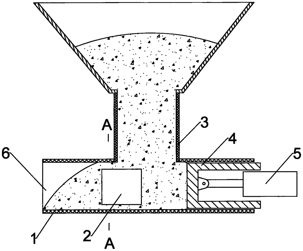
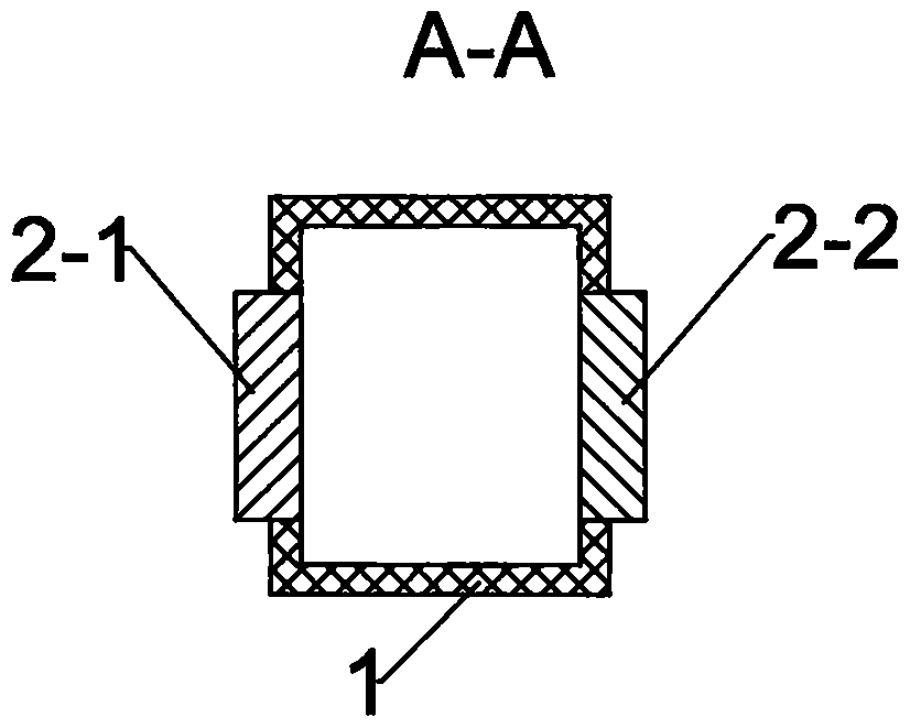
[0012] in as figure 1 , figure 2 In the first embodiment shown, the electrode group 2 is arranged horizontally opposite to both sides of the insulating flow channel 1 made of heat-resistant material, and the electrode group 2 is composed of a first electrode 2-1 and a second electrode 2-2, The arc generated by the two electrodes is in a horizontal direction. The blanking tube 3 is arranged above the electrode group 2, and the falling material can bury the arc. There is a pusher 4 at the back of the blanking tube 3. Driven by the motor 5, the reciprocating motion makes the slag in front of it push forward intermittently in the direction of the arc. A part of the waste slag burned by the arc will be melted into a glass body, and the glass body and the unburned waste slag will be pushed out from the discharge port 6 together.

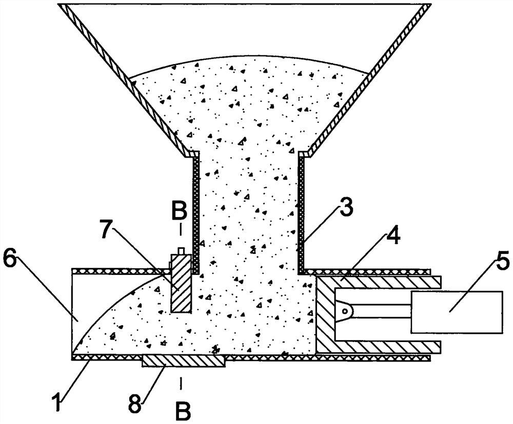
[0013] in as image 3 , Figure 4 In the second embodiment shown, the upper electrode 7 and the lower electrode 8 are vertically opposed to the upper...


PUM


Abstract

A plasma arc waste residue incineration device comprises two electrodes, namely an electrode I and an electrode II, and is characterized in that the electrode I and the electrode II are oppositely arranged in an insulating runner 1, the insulating runner 1 is provided with a blanking pipe 3 above the opposite position of the two electrodes, one end of the insulating runner 1 is a discharge port 6, and the other end of the insulating runner 1 is provided with a pusher 4. The pusher 4 is a sliding block which is driven by a motor 5 to move in a reciprocating mode or can be a spiral blade driven by the motor. Electric arcs generated by the first electrode and the second electrode are all buried in waste residues, a part of the waste residues pushed forwards must be burnt by the electric arcs, heat of the electric arcs can be almost all conducted to the part of the waste residues, and therefore when the waste residues are burnt, the electric arc heat loss is small, the burning effect is good, and the working efficiency is high.

Description

technical field [0001] The invention relates to a plasma arc incineration waste residue device, which is mainly used for the treatment of harmful wastes, such as waste residue and waste ash, and burns them into glass bodies by plasma arc for harmless treatment. Background technique [0002] Some chemical companies, hospitals, garbage disposal companies, etc. inevitably generate waste residue, waste liquid, waste ash and other harmful substances in the production process. According to environmental protection requirements, these harmful substances cannot be directly discharged, and some cannot be landfilled, or even some. It cannot be transported across regions and must be treated in a harmless manner on the spot. [0003] The commonly used treatment method is incineration, and the heat generated is used to generate electricity. However, some harmful substances cannot be burned, so people use the plasma arc burning method to deal with them, and use them to burn them into har...

Claims


Application Information

Patent Timeline
IPC IPC(8): B09B3/40B09B5/00
CPCB09B3/00B09B5/00
Inventor 姜和信康鹏赵文玉
Owner 山东鲁冶瑞宝电气自动化有限公司
Learn More