Method, device and system for monitoring wear energy of gear and electronic equipment
A monitoring device and energy technology, applied in the direction of measuring devices, testing of mechanical components, testing of machine/structural components, etc., can solve the problem of not being able to monitor gear tooth surface wear in real time, gear fatigue failure, timely detection and generation of reports, time and Problems such as high labor costs
- Summary
- Abstract
- Description
- Claims
- Application Information
AI Technical Summary
Problems solved by technology
Method used
Image

Examples
Embodiment 1
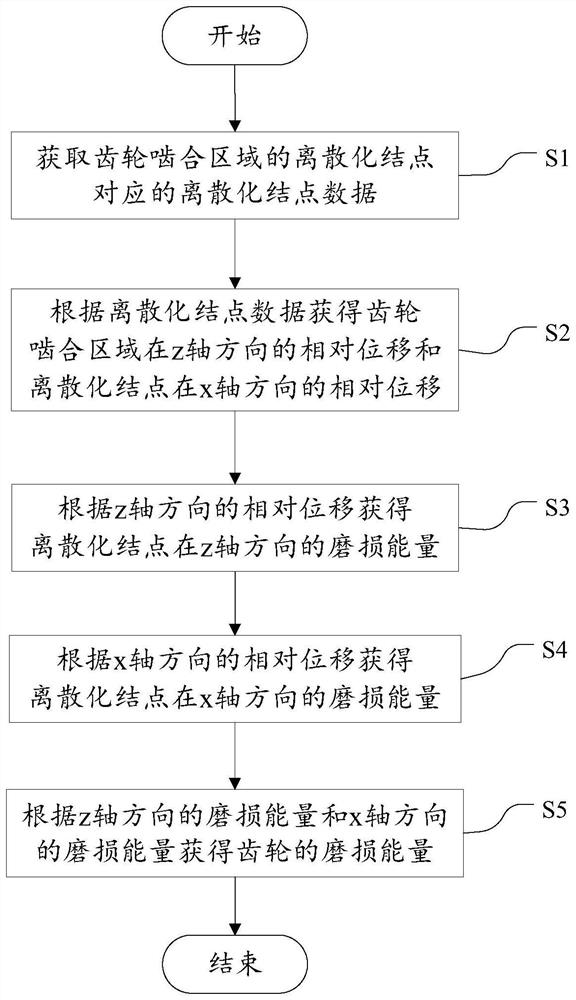
[0069] figure 1 is a schematic flowchart of the method for monitoring the wear energy of gears provided in the embodiment of the present application, as shown in figure 1 As shown, the method includes:
[0070] S1, obtain the discretized node data corresponding to the discretized nodes in the gear meshing region;
[0071] S2, obtain the relative displacement of the gear meshing region in the z-axis direction and the relative displacement of the discretized nodes in the x-axis direction according to the discretized node data;
[0072] S3, the wear energy of the discretized nodes in the z-axis direction is obtained according to the relative displacement in the z-axis direction;
[0073] S4, the wear energy of the discretized nodes in the x-axis direction is obtained according to the relative displacement in the x-axis direction;
[0074] S5, the wear energy of the gear is obtained according to the wear energy in the z-axis direction and the wear energy in the x-axis direction...
Embodiment 2
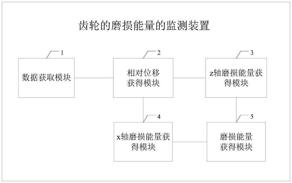
[0110] In order to implement the method corresponding to the first embodiment above, so as to achieve corresponding functions and technical effects, a device for monitoring wear energy of gears is provided below, such as image 3 As shown, the device includes:
[0111] The data acquisition module 1 is used for acquiring the discretized node data corresponding to the discretized nodes in the gear meshing area;
[0112] The relative displacement obtaining module 2 is used to obtain the relative displacement of the gear meshing region in the z-axis direction and the relative displacement of the discretized nodes in the x-axis direction according to the discretized node data;
[0113] The z-axis wear energy obtaining module 3 is used to obtain the wear energy of the discretized nodes in the z-axis direction according to the relative displacement in the z-axis direction;
[0114] The x-axis wear energy obtaining module 4 is used to obtain the wear energy of the discretized nodes i...
Embodiment 3
[0143] A system for monitoring wear energy of gears provided by an embodiment of the present application includes: a drive motor, a load motor, a drive gear, a load gear, a high-precision camera, a torque and rotational speed sensor, a device for monitoring wear energy of gears, real-time monitoring and Early warning device, lighting device;
[0144] Among them, the monitoring device for the wear energy of the gear includes:
[0145] The data acquisition module is used to acquire the discretized node data corresponding to the discretized nodes in the gear meshing area;
[0146] The relative displacement obtaining module is used to obtain the relative displacement of the gear meshing region in the z-axis direction and the relative displacement of the discretized nodes in the x-axis direction according to the discretized node data;
[0147] The z-axis wear energy acquisition module is used to obtain the wear energy of the discretized nodes in the z-axis direction according to t...
PUM
 Abstract
Description
Claims
Application Information
 - R&D Engineer
- R&D Manager
- IP Professional
- Industry Leading Data Capabilities
- Powerful AI technology
- Patent DNA Extraction
Browse by: Latest US Patents, China's latest patents, Technical Efficacy Thesaurus, Application Domain, Technology Topic.
© 2024 PatSnap. All rights reserved.Legal|Privacy policy|Modern Slavery Act Transparency Statement|Sitemap