Supercharge Your Innovation With Domain-Expert AI Agents!

Write protect switch for card connectors

A technology for card connectors and write protection, which is applied to parts, connections, and digital data protection of connection devices, and can solve problems such as inability to ensure, inability to ensure contact pressure, and inaccessibility

Inactive Publication Date: 2004-04-21
YAMAICHI ELECTRONICS +1
View PDF0 Cites 0 Cited by
  • Summary
  • Abstract
  • Description
  • Claims
  • Application Information

AI Technical Summary

Problems solved by technology

[0009] In this switch configuration, the displacement of the contact reed 100 basically depends on the height (thickness) of the button 102; The above error becomes the actual displacement of the contact reed 100, most of which cannot ensure sufficient displacement for detection
[0010] In addition, in the above-mentioned prior art, one side of the elastic displacement contact spring 100, due to the length D from the fixed part 100b for cantilever-shaped support and fixation to the abutting part 100c abutting on the write-protect key 102, and the length D from the The difference between the length E of the fixed part 100b and the contact part 100a is very small, therefore, the displacement greater than the displacement of the contact part 100c cannot be obtained at the contact part 100a; plus the above-mentioned error fluctuation and assembly tolerance, etc. , cannot ensure the necessary contact pressure to obtain electrical contact, and in the worst case, cannot detect the write-protect key position correctly and stably

Method used


Image

  • Write protect switch for card connectors
  • Write protect switch for card connectors
  • Write protect switch for card connectors

Examples


Embodiment Construction

[0016] Embodiments of the present invention will be described in detail below according to the accompanying drawings.

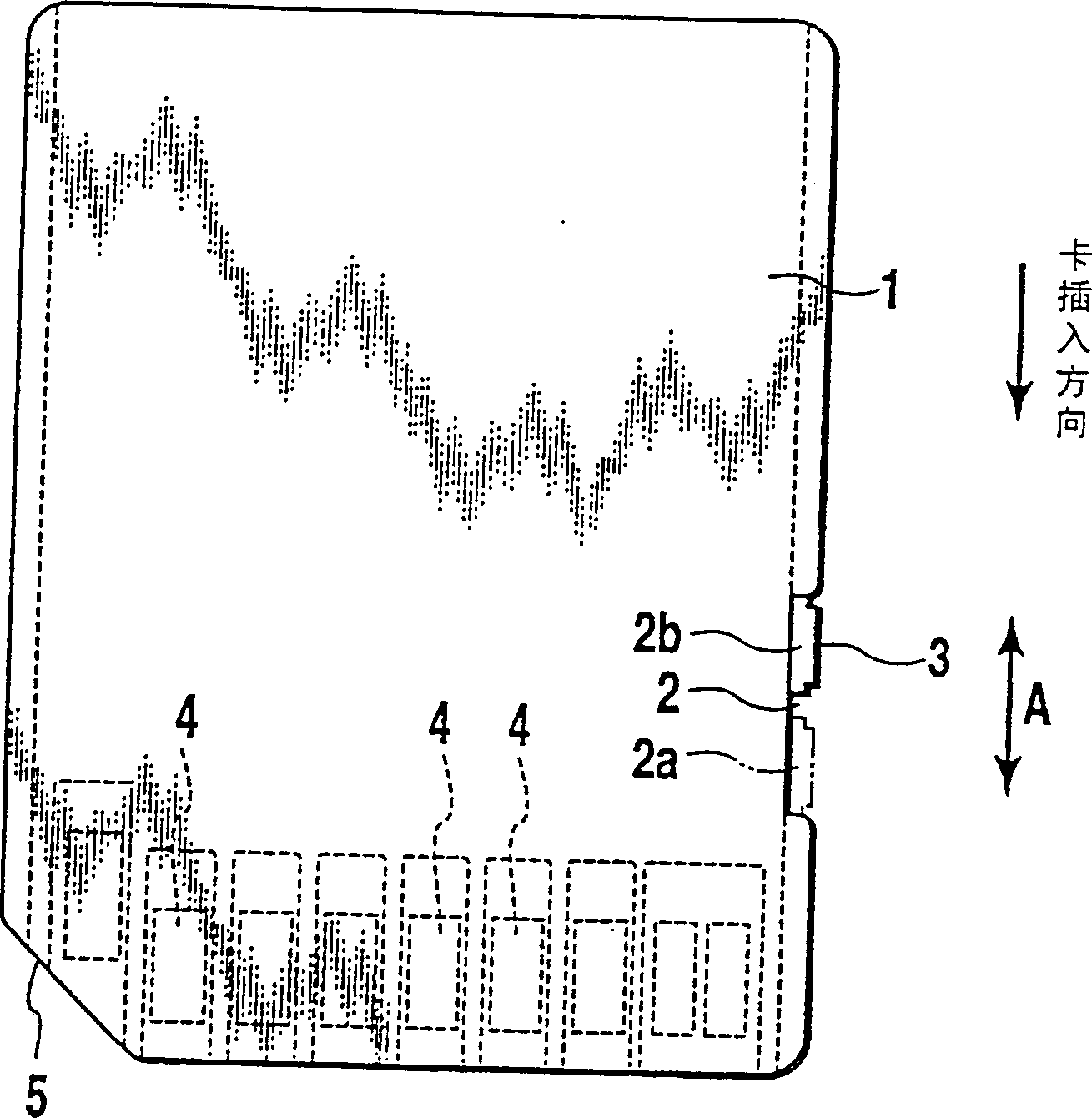
[0017] figure 1 It is a plan view showing an example of the IC card mounted in the card connector of the present invention.

[0018] On the side surface of the IC card 1, a notch 2 is formed, and a write-protect key 3 is disposed in the notch 2 so as to be slidable in the card insertion / extraction direction (arrow A direction). In this case, the write-protect key 3 can obtain two positions: the protected position (write-in prohibition position) represented by the solid line and the non-protected position (write-in permitted position) represented by the double-dot dash line, between the two positions Can slide.

[0019] The card 1 is in a write-prohibited state when the key 3 is positioned on the rear side 2b of the notch 2, and is in a write-enabled state when the key 3 is positioned on the front side 2a of the notch 2. figure 1 Not shown in , but on the...


PUM


Abstract

A write protect switch (SW) which comprises a first metal piece (50) in the form of a fixed metal piece, and a second metal piece (40) having an abutting portion (46) for abutting against a recess (2) conesponding to one slide region of a write protect button (3), the abutting portion being positioned substantially at the middle between a contact (45) and a holder (42) or positioned at a location shifted toward the holder (42) from this middle position, wherein it is ensured that both metal pieces (40, 50) reliably and stably move toward and away from each other and contact each other under required pressure, so that the position of the write protect button is accurately and reliably detected.

Description

technical field [0001] The present invention relates to the card connector that is installed in the electronic equipment such as mobile phone, telephone, PDA (personal digital assistance / special purpose digital auxiliary equipment), portable gramophone, digital camera, more specifically, it is about detecting the writing of IC card Write-protect switch at the position of the protect key. Background technique [0002] In electronic devices such as mobile phones, telephones, PDAs, and digital cameras, SIM (subscriber identity module) cards, MMC (multimedia cards), sensitive media (スマ-ブメデイア, trademarks) with built-in IC cards ), SD card (secure digital, super density), etc. are equipped with IC cards, and various function expansions and user customizations have been carried out. [0003] In this kind of IC card, in order to protect the information stored in the internal memory, it is common to take some measures to prohibit writing. Of course, when the user of the card needs ...

Claims


Application Information

Patent Timeline
Patent Type & Authority Patents(China)
IPC IPC(8): G06F12/14G06F21/60G06K7/00G06K19/073G11B23/28H01R13/629H01R13/703
CPCH01R13/703G11B23/287G06K7/0013H01R23/7094H01R12/7094G11B23/288
Inventor 宍仓诚司阪本孝广
Owner YAMAICHI ELECTRONICS
Features
  • R&D
  • Intellectual Property
  • Life Sciences
  • Materials
  • Tech Scout
  • Unparalleled Data Quality
  • Higher Quality Content
  • 60% Fewer Hallucinations
Learn More