[0042] The technical solutions in the embodiments of the present invention will be clearly and completely described below with reference to the accompanying drawings in the embodiments of the present invention. Obviously, the described embodiments are only a part of the embodiments of the present invention, but not all of the embodiments. Based on the embodiments of the present invention, all other embodiments obtained by those of ordinary skill in the art without creative efforts shall fall within the protection scope of the present invention.
[0043] In the description of the present invention, it should be understood that the orientation or positional relationship indicated by the terms "upper", "lower", "top surface", "bottom surface", etc. are based on the orientation or positional relationship shown in the accompanying drawings, only In order to facilitate the description of the present invention and simplify the description, it is not indicated or implied that the indicated positions or elements must have a particular orientation, be constructed and operated in a particular orientation, and therefore should not be construed as a limitation of the present invention. Furthermore, the terms "first" and "second" are used for descriptive purposes only and should not be construed to indicate or imply relative importance.
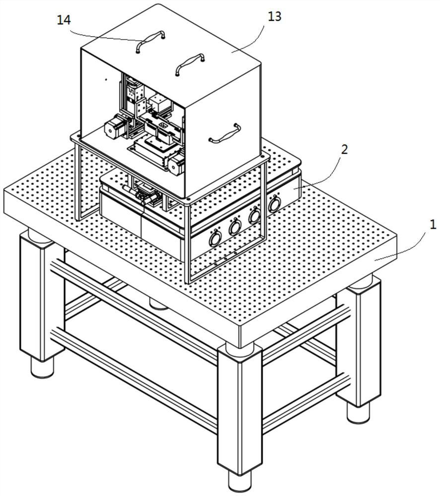
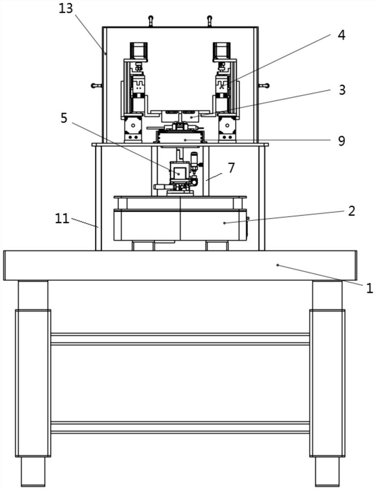
[0044] see Figure 1-Figure 7 The first aspect of the present invention provides an electronically controlled magnetic tweezers sequencing test bench, wherein the electronically controlled magnetic tweezers sequencing experimental bench includes a first platform 1, a second platform 2, a liquid pool assembly, a magnetic tweezers module 3 and an electronically controlled motion Module 4.
[0045] The first platform 1 is supported on the bottom surface, and the top support surface of the first platform 1 can be kept horizontally arranged, that is, the top support surface of the first platform 1 can always be in a horizontal state.
[0046] The second platform 2 is stacked on the top support surface of the first platform 1, and the top support surface of the second platform 2 can be kept horizontal, that is, the top support surface of the second platform 2 can always be in a horizontal state.
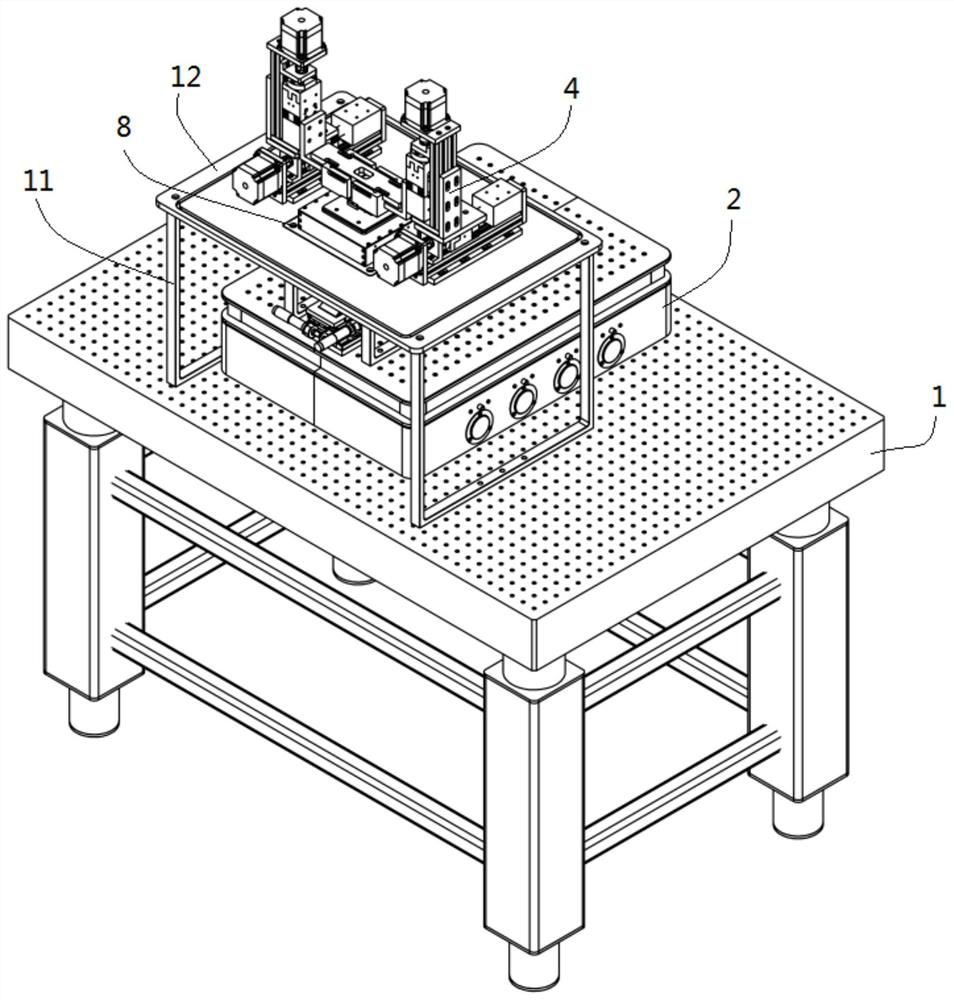
[0047] The liquid pool assembly is installed on the top support surface of the second platform 2, the electronically controlled motion module 4 is installed on the top support surface of the first platform 1, and the magnetic tweezers module 3 is installed on the driving end of the electronically controlled motion module 4. The magnetic tweezers Module 3 is located above the pool assembly.
[0048] In the electronically controlled magnetic tweezers sequencing test bench provided by the present invention, since the electronically controlled motion module 4 and the liquid pool assembly that drive the magnetic tweezers module 3 are located on the first platform 1 and the second platform 2, respectively, the electronically controlled motion module 4 and the liquid pool are located on the first platform 1 and the second platform 2 respectively. The components are not in direct contact, which avoids the vibration caused by the movement, thereby improving the accuracy of the experimental data.
[0049] In some embodiments, the liquid cell assembly includes a micro-stage 5 , a lower liquid cell 6 , a first support 7 , a first substrate 8 , a nano-stage 9 and an upper liquid cell 10 .
[0050] The micrometer displacement stage 5 is installed on the top support surface of the second platform 2. Specifically, the micrometer displacement stage 5 is also replaced by a three-dimensional precision displacement stage or the like.
[0051] The lower liquid pool 6 is installed on the micrometer displacement stage 5, and the micrometer displacement stage 5 can drive the lower liquid pool 6 to move. Specifically, the lower liquid pool 6 and the micrometer displacement stage 5 are bolted detachably connected.
[0052] The first bracket 7 is installed on the top support surface of the second platform 2, and the first base plate 8 is installed on the first bracket 7. Specifically, the first base plate 8 is detachably connected to the first bracket 7 through bolts, and the bracket is made of stainless steel. Pipes or sheets are spliced or welded.
[0053] The nanoscale stage 9 is mounted on the first substrate 8 , and specifically, the nanoscale stage 9 is detachably connected to the first substrate 8 through bolts or the like.
[0054] The upper liquid pool 10 is installed on the nanometer displacement stage 9, and the nanometer displacement stage 9 can drive the upper liquid pool 10 to move.
[0055]When using the electronically controlled magnetic tweezers sequencing test bench, first, connect one end of the DNA strand to the glass slide of the lower liquid pool 6, and control the micron stage 5 to make the upper liquid pool 10 and the lower liquid pool 6 close to each other. When the distance is close enough, Manipulate the nano-stage 9 to let the DNA strands pass through the nanopores opened on the chip of the upper liquid pool 10; then, add magnetic beads to the upper liquid pool 10, the magnetic beads and the DNA strands are linked, and make the magnetic tweezers module 3 close to the upper liquid pool 10 Pull up the magnetic beads to straighten the DNA strand, and then move the nanoshift stage 9 to detect the base sequence on the DNA strand.
[0056] In some embodiments, the electro-controlled magnetic tweezers sequencing experiment bench further includes a second support 11 and a second substrate 12 .
[0057] The second bracket 11 is installed on the top support surface of the first platform 1 , the second base plate 12 is installed at the top end of the second bracket 11 , and the second base plate 12 and the first base plate 8 are arranged at a predetermined gap. The electronically controlled motion module 4 mounted on the second substrate 12 . The setting of the gap between the second substrate 12 and the first substrate 8 avoids direct contact between the electronically controlled motion module 4 and the liquid pool assembly, avoids vibration caused by movement, and improves the accuracy of experimental data.
[0058] Further, the present invention discloses that the top surface of the first base plate 8 is provided with a first annular groove.
[0059] The bottom end surface of the second base plate 12 is provided with a second annular groove, the outer wall of the first annular groove is placed in the second annular groove, and the outer wall of the first annular groove and the inner wall of the second annular groove are provided with a gap, and the second annular groove The outer wall is placed in the first annular groove, and the outer wall of the second annular groove and the inner wall of the first annular groove are arranged with a gap. The arrangement of the first annular groove and the second annular groove is convenient for installation on the basis of avoiding direct contact between the electronically controlled motion module 4 and the liquid pool assembly. In some embodiments, the first platform 1 is an air-floating optical platform. The air-floating optical platform includes a honeycomb structure, a vibration isolation inner core and a superconducting magnetic vibration isolation platform panel. The floating optical platform has high strength and is stable and reliable; the vibration isolation inner core The ultra-thin airbag of conforming material and the multi-hole quasi-laminar flow damping technology with additional diffusion ports are adopted, which have good vibration isolation performance and stable system.
[0060] The air-floating optical platform adopts the principle design of film-type rubber air spring. When the support rushes into the rated compressed air, the rubber air spring in the support starts to work, and the support is in the working state of air cushion.
[0061] When the air-floating optical platform is manufactured, a very flat platform panel is first processed, and then the platform panel is placed on the four connected airbags to ensure the level of the platform panel. The first platform 1 is provided with a plurality of mounting holes. Specifically, the mounting holes on the first platform 1 are engineering threaded holes arranged in a square on the platform panel, and the optical elements can be fixed with these holes and corresponding screws. Even if the platform panel is pressed, it will automatically return to the level due to the air bag.
[0062] Vibration isolation method of air-floating optical platform: air spring, vibration isolation rubber; adjustment method: automatic leveling; damping method: multi-hole air damping; flatness ≤ 0.05mm/㎡, surface roughness < 0.8um (matte surface treatment), amplitude ≤ 5um, vibration isolation efficiency: 95%, load ≤ 200kg.
[0063] In some embodiments, the second platform 2 is a table-type air-floating platform, the foundation support adopts composite material solid damping vibration isolation, the honeycomb-shaped support structure is stable and reliable, and the honeycomb-type design greatly reduces the weight of the table-type air-floating platform, and its rigidity However, it has increased to ensure maximum mechanical stability and improved damping. The top support surface of the tabletop air flotation platform uses pressure bonding to obtain a good flatness, and a grinding process to achieve a smooth but non-reflective surface. The honeycomb core, surface panels and side walls of the desktop air flotation platform are permanently and firmly bonded by special high-strength adhesives, without elasticity, sliding or aging. The surface plate, inner core, and side walls of the table-type air flotation platform are all made of steel, and obtain the same thermal expansion coefficient, so that the table-type air flotation platform can expand or contract as a whole, so as to ensure the structural integrity of the optical vibration isolation platform and prevent the optical vibration isolation platform. Internal stress buildup occurs under temperature cycling conditions. The table-type air-floating platform adopts standard damping form plus air-floating vibration isolation, flatness ≤0.05mm/㎡, surface roughness ≤0.8um-1.6um, amplitude ≤5um, vibration isolation efficiency: 97%, load ≤120kg. The second platform 2 is provided with a plurality of mounting holes. Specifically, the mounting holes on the second platform 2 are engineering threaded holes arranged in a square on the platform panel, and the optical elements can be fixed with these holes and corresponding screws.
[0064] In some embodiments, the electronically controlled magnetic tweezers sequencing test bench further includes a shielding box 13 , the shielding box 13 is buckled on the second substrate 12 , and the shielding box 13 covers the magnetic tweezers module 3 , the electronically controlled motion module 4 , and the liquid filling The pool 10 and the lower liquid pool 6 avoid the external environment interfering with the test and further improve the test accuracy.
[0065] Further, the present invention discloses that a patch clamp 15 is also installed on the first substrate 8 , and the patch clamp 15 is also placed in the shielding box 13 .
[0066] Specifically, the present invention discloses that the shielding box 13 is a Faraday cage. It should be noted that the shielding case 13 can also be made of other materials.
[0067] Further, the present invention discloses that the shielding box 13 is provided with a handle 14, and the number of the handle 14 is at least one.
[0068] In some embodiments, the present invention discloses that the electronically controlled motion module 4 is a linear module. Specifically, the repetitive positioning accuracy of the electronically controlled motion module 4 is ±0.02 mm; the maximum vertical load: 15kg; the maximum horizontal load: 25kg; The motion module 4 includes a precision lead screw and a servo motor, and the servo motor has a brake.