
Device for laying denitration catalyst on ceramic filter element

The technology of denitration catalyst and ceramic filter element is applied in the device, chemical instrument and method, separation method and other directions of coating liquid on the surface, which can solve the problems of inability to ensure the uniformity and laying of liquid catalyst.

Pending Publication Date: 2022-07-22
HEFEI FOUND TECH
View PDF3 Cites 0 Cited by
  • Summary
  • Abstract
  • Description
  • Claims
  • Application Information

AI Technical Summary

Problems solved by technology

[0008] The common problem in the above-mentioned documents 1, 2, and 3 is that it is impossible to ensure that the liquid catalyst is evenly laid on the ceramic carrier.

Method used


Image

  • Device for laying denitration catalyst on ceramic filter element
  • Device for laying denitration catalyst on ceramic filter element
  • Device for laying denitration catalyst on ceramic filter element

Examples


Embodiment Construction

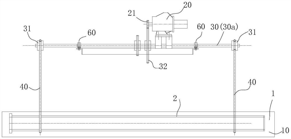
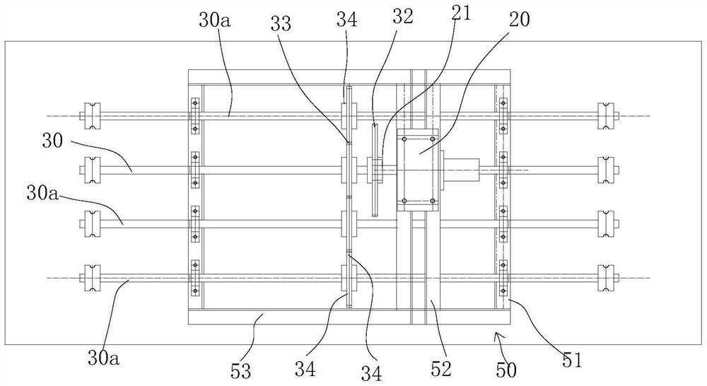
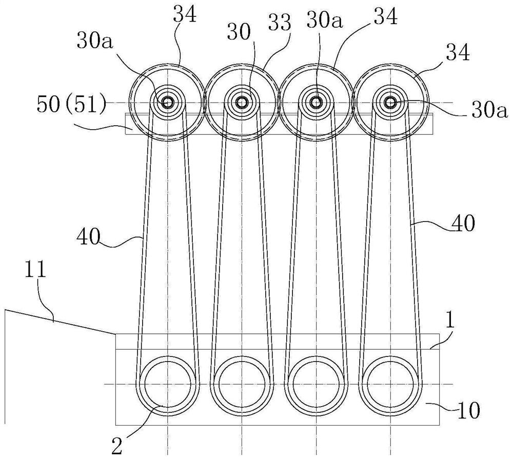
[0015] like figure 1 , 2 As shown in 3 and 3, the device for laying the denitration catalyst on the ceramic filter element includes a liquid medicine pool 10 containing the denitration catalyst liquid medicine 1. Above the pool mouth of the liquid medicine pool 10 is a main rotating shaft 30 driven by a motor 20. The main rotating shaft 30 is arranged horizontally, and the annular soft The upper end of the belt 40 is hung on the main rotating shaft 30, the annular soft belt 40 is of equal length and is arranged at several intervals along the length direction of the main rotating shaft 30, and the lower end of the annular soft belt 40 is hung around the ceramic filter element tube 2 to be treated. On the tube body, the ceramic filter tube 2 is immersed in the denitration catalyst liquid 1.

[0016] Since most of the denitration catalysts contain heavy metal oxides and have a high density, the aqueous solution cannot be left standing after stirring evenly, otherwise it is easy ...


PUM


Abstract

According to the device for laying the denitration catalyst on the ceramic filter element, the concentration of denitration catalyst liquid medicine is homogenized, the denitration catalyst liquid medicine is evenly laid on a ceramic filter element pipe, the denitration catalyst liquid medicine is placed in a liquid medicine pool, and the lower end of an annular soft belt is wound and hung on a pipe body of the ceramic filter element pipe to be treated; the ceramic filter element tube is suspended according to the self weight and is immersed in the denitration catalyst liquid medicine, the main rotating shaft drives the ceramic filter element tube to rotate in the denitration catalyst liquid medicine through the annular soft belt when rotating, the concentration of all positions of the denitration catalyst liquid medicine is homogenized, and in the rotating process of the ceramic filter element tube, the denitration catalyst liquid medicine is uniformly dispersed in the ceramic filter element tube. And the medicament applied to each part of the tube body is also very uniform.

Description

technical field [0001] The invention relates to a flue gas treatment technology, in particular to a device for laying a denitration catalyst on a ceramic filter element. Background technique [0002] Due to the increasing awareness of environmental protection, environmental protection regulations have become more stringent, and emission of smoke and dust is a problem that must be faced by all smoke-related enterprises such as smelting, thermal power, and cement. [0003] At present, the flue gas treatment scheme is generally adopted. First, denitrification and desulfurization are implemented. The denitration and desulfurization schemes are divided into wet, dry and dry-wet mixed treatment schemes. The flue gas after desulfurization and denitration is dedusted again, and the whole process chain is long. , There are many process equipment, high maintenance cost, huge area and high investment. [0004] The name is "denitration catalyst and its preparation method and applicatio...

Claims


Application Information

Patent Timeline
IPC IPC(8): B05C3/10B05C13/02B05C11/08B01D53/86B01D53/56
CPCB05C3/10B05C13/02B05C11/08B01D53/8625
Inventor 王德富经文贤方鹏严永青曹伟
Owner HEFEI FOUND TECH
Learn More