Method for controlling temperature of battery comprising lithium salt
A technology for batteries and unit cells, applied in the temperature field of batteries, can solve problems such as harmful contributions to the greenhouse effect, and achieve the effects of improved life, high ionic conductivity, and good temperature.
- Summary
- Abstract
- Description
- Claims
- Application Information
AI Technical Summary
Problems solved by technology
Method used
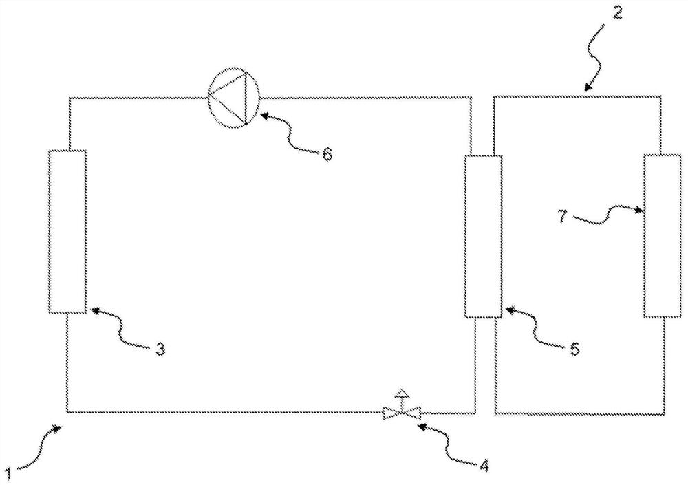
Image

Examples
Embodiment 1
[0294] Examples 1 and 2 - Preparation of LiFSI (according to the present invention)
[0295] At the end of the process described in WO2015 / 158979, a crude LiFSI solution in butyl acetate was obtained. The LiFSI solution is purified by liquid-liquid extraction of the salt with deionized water to form an aqueous solution, followed by liquid-liquid extraction of the lithium bis(fluorosulfonyl)imide salt from the aqueous solution with butyl acetate . The resulting solution is subjected to a concentration stage to produce a composition comprising more than 30% by weight of dry extract, characterized in that the extract contains more than 99.75% by weight of LiFSI and a total weight content of chloride, sulfate and fluoride ions Strictly greater than 0 and less than 500 ppm. The composition was then subjected to crystallization and filtration stages to produce the LiFSI of Example 1 .
[0296] The LiFSI of Example 2 was obtained according to a similar method.
Embodiment 3
[0297]Example 3 - Preparation of LiFSI (comparison)
[0298] At the end of the process described in WO2015 / 158979, a crude LiFSI solution in butyl acetate was obtained. Purification of the LiFSI solution comprising liquid-liquid extraction of the salt with deionized water to form an aqueous solution, followed by liquid-liquid extraction of the lithium bis(fluorosulfonyl)imide salt from the aqueous solution with butyl acetate . The resulting solution is subjected to a concentration stage to produce a composition comprising a dry extract characterized in that the extract contains less than 99.75 wt% LiFSI and has a total weight content of chloride, sulfate and fluoride strictly greater than 600 ppm.
[0299] The composition was then subjected to crystallization and filtration stages to produce the LiFSI of Example 3.
Embodiment 4
[0300] Example 4 - Characterization
[0301] Cyclic voltammetry tests were performed. For this, a CR2032 coin cell was fabricated, which was equipped with an aluminum plate with a diameter of 20 mm as the working electrode, a lithium metal pellet with a diameter of 8 mm as the reference electrode, and a glass fiber separator with a diameter of 18 mm, which was soaked with 12 drops (0.6 ml) of different compositions of 1 mol / l LiFSI solutions in a solvent mixture consisting of ethylene carbonate and ethyl methyl carbonate (CAS=623-53-0) in a volume ratio of 3 / 7.
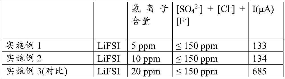
[0302] Subsequently, a voltage sweep was performed at the terminals of the 4.5V coin cell. Two preliminary scans are performed to enable the formation of passivation layers (eg SEI and passivation of aluminum). Subsequently, the resulting 4.5 V oxidation current (after two scans) was measured and recorded. The values are as follows:
[0303] [Table 2]
[0304]
[0305] The observed oxidation currents can ref...
PUM
 Abstract
Description
Claims
Application Information
 - Generate Ideas
- Intellectual Property
- Life Sciences
- Materials
- Tech Scout
- Unparalleled Data Quality
- Higher Quality Content
- 60% Fewer Hallucinations
Browse by: Latest US Patents, China's latest patents, Technical Efficacy Thesaurus, Application Domain, Technology Topic, Popular Technical Reports.
© 2025 PatSnap. All rights reserved.Legal|Privacy policy|Modern Slavery Act Transparency Statement|Sitemap|About US| Contact US: help@patsnap.com