Supercharge Your Innovation With Domain-Expert AI Agents!

Estimation device, vacuum valve, and vacuum pump

A deduction device and vacuum pump technology, applied in the direction of pumps, axial flow pumps, pump control, etc., can solve problems such as inability to rotate

Pending Publication Date: 2022-07-26
SHIMADZU SEISAKUSHO CO LTD
View PDF9 Cites 0 Cited by
  • Summary
  • Abstract
  • Description
  • Claims
  • Application Information

AI Technical Summary

Problems solved by technology

In a turbomolecular pump, the rotor rotates at high speed with a gap between it and the stator. However, reaction products during etching accumulate inside the pump and eventually fill up the gap between the rotor and the stator and fix them. Therefore, rotation may not be possible.

Method used


Image

  • Estimation device, vacuum valve, and vacuum pump
  • Estimation device, vacuum valve, and vacuum pump
  • Estimation device, vacuum valve, and vacuum pump

Examples


no. 1 approach -

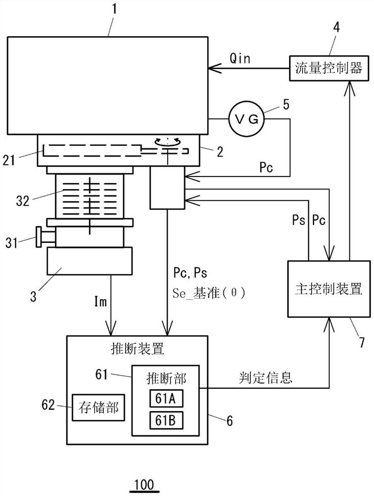
[0043] figure 1 This is a block diagram showing a schematic configuration of the vacuum processing apparatus 100 . Examples of the vacuum processing apparatus 100 include an etching apparatus, a film forming apparatus, and the like. The vacuum processing apparatus 100 includes a vacuum chamber 1 for performing a process, a vacuum valve 2 installed in the vacuum chamber 1 , a vacuum pump 3 installed in the vacuum chamber 1 via the vacuum valve 2 , and a control for the gas introduced into the vacuum chamber 1 . The flow controller 4 for controlling the flow rate of the vacuum chamber 1 , the vacuum gauge 5 for measuring the pressure of the vacuum chamber 1 , the estimation device 6 , and the main control device 7 for controlling the vacuum processing apparatus 100 .

[0044] The vacuum valve 2 is an automatic pressure control valve, which automatically adjusts the opening degree θ of the valve body 21 so that the chamber pressure Pc becomes Target pressure Ps. The vacuum val...

Deformed example 1

[0145] In the above-described embodiment, it is assumed that the process information data set is generated, the accumulation information data set obtained by adding the motor current value Im input from the vacuum pump 3 to the process information data set is generated, and the accumulation information data used for the determination of the accumulation amount is assumed. The extraction of the set and the determination of the accumulation amount based on the extracted accumulation information data set are all performed by the inference device 6 . However, for example, a determined data set (a data set containing only process gas conditions) for each process event that does not contain the motor current value Im can be sent from the inference device 6 to the vacuum pump 3 or the vacuum valve 2, and at the vacuum pump 3 or vacuum In the valve 2 , the determination of the accumulation amount is performed by adding the motor current value Im and the measurement time Time_msr to the...

Deformed example 2

[0148] exist figure 1 In the system configuration shown, the estimating device 6 is connected in parallel with the vacuum pump 3 and the vacuum valve 2 through a communication line to acquire information from the vacuum pump 3 and the vacuum valve 2, but the vacuum pump 3 may be communicated via RS485 communication or the like. , the vacuum valve 2 and the inference device 6 are connected in sequence in a daisy-chain connection. The motor current value Im of the vacuum pump 3 is sent to the estimation device 6 via the vacuum valve 2 .


PUM


Abstract

The invention provides an estimation device capable of extracting and classifying state characteristic values of a vacuum pump with good precision. An estimation device (6) estimates the process gas condition of a system (100) in which a vacuum chamber (1) into which a gas is introduced and which is subjected to a process treatment is exhausted by a vacuum pump (3) mounted via a vacuum valve (2), and the vacuum chamber (1) is subjected to a process treatment by a vacuum pump (3) mounted via a vacuum valve (2). The estimation device (6) estimates a first process gas condition including information on the gas type and the gas flow rate of the introduced gas, on the basis of correlation data between the valve body opening degree of the vacuum valve (2) and the effective exhaust speed of the system (100), which are related to a predetermined gas type, and on the basis of the chamber pressure (Pc) of the vacuum chamber (1).

Description

technical field [0001] The present invention relates to an estimating device for estimating process conditions processed in a vacuum device, a vacuum valve and a vacuum pump having the estimating device. Background technique [0002] Turbomolecular pumps are used as exhaust pumps for various semiconductor manufacturing apparatuses, but when exhaust is performed in an etching process or the like, reaction products accumulate inside the pump. In a turbomolecular pump, the rotor rotates at a high speed with a gap between the rotor and the stator. However, reaction products during etching accumulate inside the pump and eventually fill the gap between the rotor and the stator to be fixed. Therefore, the rotating operation may not be possible. Regarding the accumulation of such reaction products, for example, as described in Patent Document 1 and Patent Document 2, a method of evaluating the accumulation amount based on the increase in the motor current value has been proposed. I...

Claims


Application Information

Patent Timeline
Patent Type & Authority Applications(China)
IPC IPC(8): F04D19/04F04D27/00
CPCF04D19/04F04D27/00F04D19/042F04D27/001F05D2260/821F05D2270/3011F05D2270/335F04D27/0253F05D2270/3061F05D2210/20F05D2260/80F05D2260/607F05D2210/12F04D27/008H01L21/67253F16K37/0083F16K31/02
Inventor 小崎纯一郎
Owner SHIMADZU SEISAKUSHO CO LTD
Features
  • R&D
  • Intellectual Property
  • Life Sciences
  • Materials
  • Tech Scout
  • Unparalleled Data Quality
  • Higher Quality Content
  • 60% Fewer Hallucinations
Learn More