Cylinder type clamping and pressing upender for industrial furnace production line
A production line and turning machine technology, applied in the field of turning machines, can solve the problems of affecting use and cumbersome cleaning work, and achieve the effect of improving safety and avoiding accidental slipping
- Summary
- Abstract
- Description
- Claims
- Application Information
AI Technical Summary
Problems solved by technology
Method used
Image

Examples
Example Embodiment
[0037] Example 1:
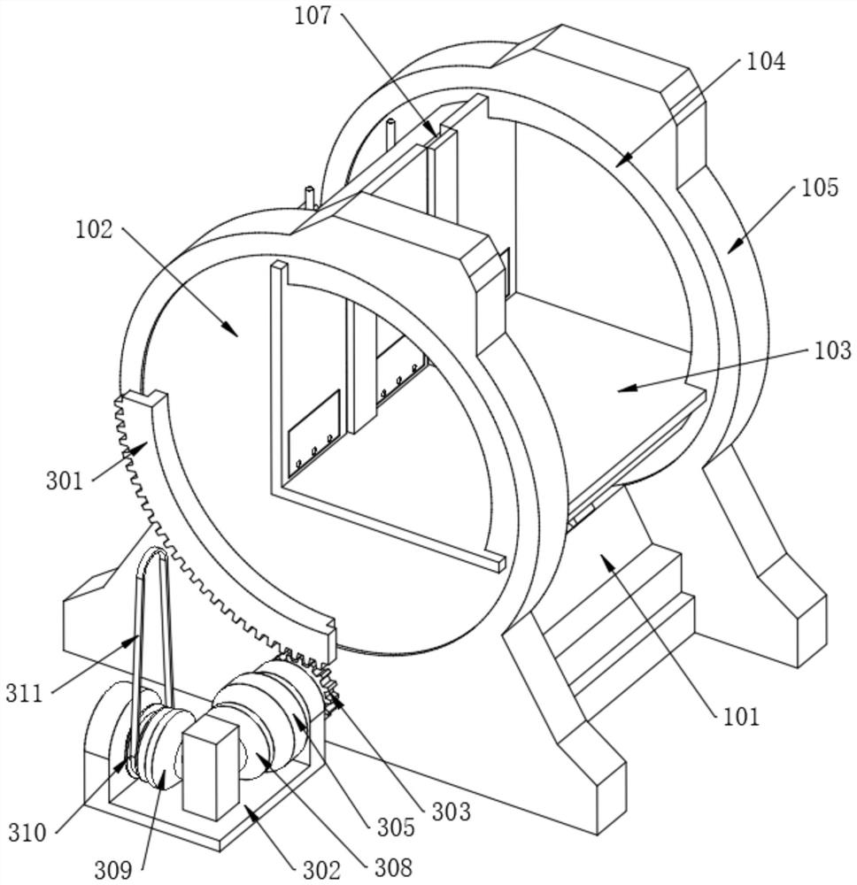
[0038] Refer to the attached image 3 The two ends of one side surface of the right-angle table 103 are fixedly provided with embedded grooves 107, and the outer wall of one side of the machine base 101 away from the material conveying rack 2 is rotated and installed with a working cylinder 106. The output end of the working cylinder 106 is connected to the turning table 102. One side of the outer wall edge is rotatably connected, the top two sides of the base 101 are fixedly provided with annular rails 105, both ends of the right-angle table 103 are fixedly provided with inner ring bodies 104, and the inner ring body 104 is movably embedded in the interior of the annular rail 105, One end of the machine base 101 is fixedly assembled with a conveying frame 2, and a guide roller 21 is installed in the interior of the conveying frame 2 equidistantly. When the side surface of the right-angle table 103 is on, the working cylinder 106 is activated, and then the...
Example Embodiment
[0043] Embodiment 2:
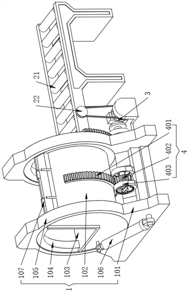
[0044] Refer to the attached Figure 5 , the outer wall of one side of the machine base 101 is provided with a tight brake assembly 4, and the tight brake assembly 4 also includes a wheel shaft 404, the outer wall of the turning table 102 away from the right-angle table 103 is fixedly provided with a local gear ring 2 401, and the wheel shaft 404 is rotated and installed on the machine base. One side of the outer wall of 101, the middle surface of the wheel shaft 404 is fixedly installed with the second gear 402, and the second gear ring 401 meshes with the second gear 402. When the turning table 102 has an accident and rotates rapidly, due to the partial ring gear 401 and the second gear With the meshing of the second gear 402, the rotational speed of the axle 404 will also increase rapidly.
[0045] Refer to the attached Image 6 , both ends of the wheel shaft 404 are fixedly connected with trigger rods 405, the outer wall of the machine base 101 is ...
Example Embodiment
[0047] Embodiment three:
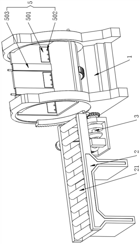
[0048] Refer to the attached Figure 7 , the inside of the turning table 102 is located on the side of the right-angle table 103 and is fixedly provided with a turning dust cleaning assembly 5. The turning dust cleaning assembly 5 also includes a bearing plate 503, and the bearing plate 503 is movably embedded in the interior of the embedded groove 107. The turning table 102 The inner side of the load-bearing plate 503 is installed with an empty pipe body 504 at equal distances, and the inner side of the load-bearing plate 503 is fixedly connected with a piston 505 at an equal distance. A spring 506 is provided on one side of the 505. When the material of the plate material is turned from one side surface of the right-angle table 103 to the other side surface, the plate will squeeze the bearing plate 503. After the bearing plate 503 is under pressure, the bearing plate 503 will be pressed. Moving inside the insert groove 107 , at the same time, the ...
PUM
 Abstract
Description
Claims
Application Information
 - R&D Engineer
- R&D Manager
- IP Professional
- Industry Leading Data Capabilities
- Powerful AI technology
- Patent DNA Extraction
Browse by: Latest US Patents, China's latest patents, Technical Efficacy Thesaurus, Application Domain, Technology Topic.
© 2024 PatSnap. All rights reserved.Legal|Privacy policy|Modern Slavery Act Transparency Statement|Sitemap