Check patentability & draft patents in minutes with Patsnap Eureka AI!

Disc holder for disc player

A technology for a clamping device and a player, which is applied in the direction of instruments, recording information storage, etc., can solve the problems of the disc leaving the clamping device, the difficulty in setting the clamping force, and the increase in the clamping force.

Inactive Publication Date: 2004-10-06
SAMSUNG ELECTRONICS CO LTD
View PDF0 Cites 0 Cited by
  • Summary
  • Abstract
  • Description
  • Claims
  • Application Information

AI Technical Summary

Problems solved by technology

If the disc becomes thicker, the combined clamping force becomes smaller, and the disc will fall out of the clamping device; if the disc becomes thinner, the combined clamping force becomes larger, and the disc cannot be removed from the clamping device smoothly
Therefore, it is difficult to set an appropriate clamping force that can be applied to all thickness variations

Method used


Image

  • Disc holder for disc player
  • Disc holder for disc player
  • Disc holder for disc player

Examples


Embodiment Construction

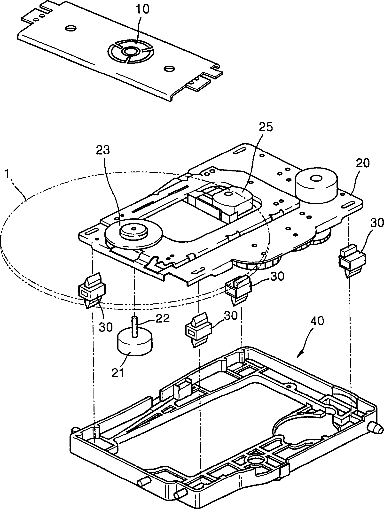
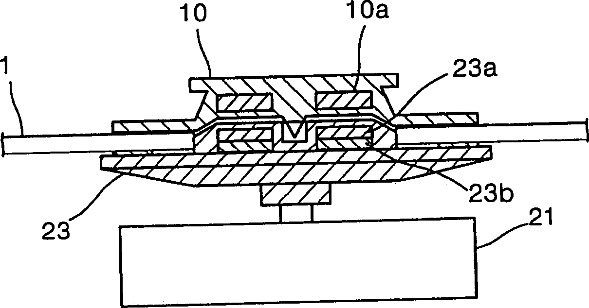
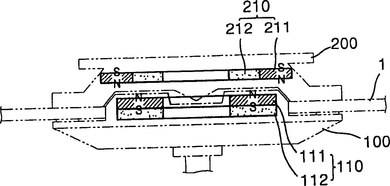
[0017] image 3 Shown is a disc holding device according to a first embodiment of the present invention. refer to image 3 , the disc clamping device includes: a turntable 100 for placing the disc 1 , a disc clamper 200 , a first magnet 110 , and a second magnet 210 . The holder 200 is opposite to the turntable 100 and holds the disc 1 placed in the turntable 100 . The first magnet 110 and the second magnet 210 are installed in the turntable 100 and the clamper 200 respectively, and provide clamping force generated by magnetic force.

[0018] The first magnet 110 includes a first magnet 111 and a first yoke 112 . The first yoke 112 is installed on the bottom surface of the first magnet 111 .

[0019] The second magnet 210 includes a second magnet 211 and a second yoke 212 . The second yoke 212 is positioned opposite the inner annular region of the first magnet 111 . A magnetic attractive force acts between the first magnet 111 and the second yoke 212 . The second magnet...


PUM

PropertyMeasurementUnit
thicknessaaaaaaaaaa

Abstract

A disk clamping apparatus for a disk player includes a turntable for receiving a disk, a disk clamper which clamps the disk placed on the turntable, and first and second magnetic bodies which are mounted in the corresponding turntable and the disk clamper and provide a clamping force to the disk by acting a reciprocal magnetic force on the turntable and the disk clamper. The first and second magnetic bodies are opposite to each other and partially overlap each other. In the disk clamping apparatus having the above structure, the variation in a clamping force caused by the variation in thickness of disks, received by the disk clamping apparatus, is very small. Accordingly, clamping and de-clamping of the disks having different thickness can be smoothly performed.

Description

technical field [0001] The invention relates to a disk clamping device of a disk player. Background technique [0002] In general, a disk player is a device for recording information on or reproducing information from recording media such as CDs, CD-ROMs, and DVDs. Such as figure 1 As shown, the disc player includes: a core base 40 , a core board 20 , a spindle motor 21 , a turntable 23 , a disc holder 10 and an optical head 25 . The movement base 40 has a hinge connected to the housing (not shown) so that it can rotate in a vertical plane. The movement board 20 is provided with a pre-installed buffer 30 to be connected to the movement base 40 . The spindle motor 21 is installed on the core board 20 and provides rotational power for the disc 1 . The turntable 23 is connected with the rotating shaft 22 of the spindle motor 21 , and the disc 1 is placed on the turntable 23 . The disk holder 10 is mounted on the upper part of the housing, facing th...

Claims


Application Information

Patent Timeline
Patent Type & Authority Patents(China)
IPC IPC(8): G11B17/028
CPCG11B17/0284G11B17/028
Inventor 金石中郑钟三李容勋崔汉国
Owner SAMSUNG ELECTRONICS CO LTD
Features
  • R&D
  • Intellectual Property
  • Life Sciences
  • Materials
  • Tech Scout
  • Unparalleled Data Quality
  • Higher Quality Content
  • 60% Fewer Hallucinations
Learn More