Check patentability & draft patents in minutes with Patsnap Eureka AI!

Antijamming signal transferring cable and high-speed high-amplitude pulse current sensor

A current sensor, high-amplitude pulse technology, applied in the direction of measuring current/voltage, cables with double-stranded/quad-stranded, instruments, etc., can solve the problem of no Hall current sensor, no measurement As a result, magnetic shielding cannot be achieved, etc.

Inactive Publication Date: 2004-11-24
王德言 +1
View PDF0 Cites 0 Cited by
  • Summary
  • Abstract
  • Description
  • Claims
  • Application Information

AI Technical Summary

Problems solved by technology

[0004] 1. The conventional Hall current sensor adopts a ferromagnetic magnetic circuit, which is limited by the saturation flux density of ferromagnetic materials. The upper limit current that this Hall current sensor can measure is limited by its power consumption and volume, and the capacity has not yet been reached. Ten thousand ampere Hall current sensor coverage;
[0005] 2. Instead of using a ferromagnetic magnetic circuit, the Hall chip is directly placed near the current-carrying conductor of the measured current. Although the measurable current amplitude is almost unlimited, it requires the transmission line connected to the Hall chip to change at a high speed. It has excellent anti-interference performance in the non-uniform strong magnetic field. At present, the transmission cable connected to the Hall chip usually uses a multi-core shielded cable. Each core wire of this cable is a single or multiple copper wires wrapped by a plastic sheath. , when this type of cable (even if its core wire is a twisted pair) is connected to the electrodes or leads of the Hall chip, a large lead loop area will be formed at the connection, and the large-area lead loop is connected to the measured high-speed high-amplitude The cross-linking of the magnetic field lines generated by the value current will generate a large additional induction signal proportional to the rate of change of the measured current with time, and the superposition of the additional induction signal and the Hall signal proportional to the measured current will greatly improve the measurement accuracy. reduced, or even impossible to obtain correct measurement results
In addition, ordinary multi-core shielded cables can only achieve electrical shielding but not magnetic shielding. When this kind of cable is in a high-speed changing strong pulse magnetic field, the core wire of the cable will also be induced with additional induction signals that seriously affect the measurement results.

Method used


Image

  • Antijamming signal transferring cable and high-speed high-amplitude pulse current sensor
  • Antijamming signal transferring cable and high-speed high-amplitude pulse current sensor
  • Antijamming signal transferring cable and high-speed high-amplitude pulse current sensor

Examples


Embodiment 1

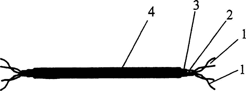
[0056] The structure of the high anti-jamming signal transmission cable in this embodiment is as follows: figure 1 , figure 2 As shown, the enamelled twisted pair 1 is formed by two enameled wires with a diameter of 0.12 mm twisted evenly and tightly. 4. Cover in turn two sets of enamelled twisted pairs that are independent of each other and placed in a free bend.

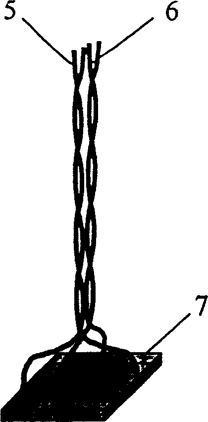
[0057] according to image 3 As shown, the two signal electrodes of the Hall chip 7 are directly welded to the ends of the two signal leads formed after the signal transmission line 5 of the high anti-interference signal transmission cable is bifurcated, and the two power supply electrodes are directly connected to the power supply of the high anti-interference signal transmission cable. The ends of the two power lead wires formed after the transmission line 6 is bifurcated are welded, and the "cross-section centers" of the two signal lead wires are symmetrically distributed in such as Image 6 The two sides o...

Embodiment 2

[0064] The structure of the high anti-interference signal transmission cable in the present embodiment is the same as that of Embodiment 1, as figure 1 , figure 2 shown. In this embodiment, a 0.2mm enameled wire is used to make an enameled twisted pair. The structure of the high-speed high-amplitude pulse current sensor is as follows: Figure 10 , Figure 11 , Figure 12 , Figure 13 , Figure 14, Figure 15 , Figure 16 As shown, it includes a printed board 21 , a Hall chip 7 , a high anti-interference signal transmission cable, a shield 19 , a conductor segment 26 , a substrate 24 and a housing 27 . There are two sets of printed lines 22 and 23 on the printed board 21, which are the pins connecting the Hall chip signal electrodes and the power electrodes. And close to the electrode arrangement on the corresponding Hall chip, such as Figure 11 As shown; the signal leads and power leads formed after the two sets of transmission lines of the high anti-interference si...


PUM


Abstract

The antijamming signal transferring cable consists of enameled twisted pair line, insulating layer, shield layer and protective jacket. The high-speed and high-amplitude pulse current sensor includes the antijamming signal transferring cable, Hall chip, shielding cover and conductor section. The antijamming signal transferring cable is split into two signal lines connected to the two signal electrodes of the Hall chip and the power transmission line are connected to the power electrodes of the Hall chip. The Hall chip is installed inside the shield cover, the shield cover is connected with the shielding layer of the antijamming signal transferring cable to constitute one current sensing element and the current sensing element is connected to the conductor section to constitute a current sensor.

Description

1. Technical field [0001] The invention relates to a signal transmission cable with high anti-interference ability in a high-speed changing non-uniform strong magnetic field and a current sensor for measuring high-speed high-amplitude pulse current. 2. Background technology [0002] For the measurement of high-speed and high-amplitude pulse currents, current sensors made of Rogowski coils are generally used at present (see "Lightning Current Automatic Monitoring System", Lin Yunzhi, etc., Department of Electrical Engineering, Tsinghua University, "New Technology of Electrical Engineering and Energy", P59-62, 2000, p. 4 issues). Since the output voltage of this type of current sensor is proportional to the rate of change of the measured current over time rather than the amplitude of the measured current, the output voltage needs to be integrally transformed in actual use, which not only increases the cost of signal processing difficult and will reduce the measurement accurac...

Claims


Application Information

Patent Timeline
Patent Type & Authority Patents(China)
IPC IPC(8): G01R15/00G01R19/00H01B11/06
Inventor 王富元王德言
Owner 王德言
Features
  • R&D
  • Intellectual Property
  • Life Sciences
  • Materials
  • Tech Scout
  • Unparalleled Data Quality
  • Higher Quality Content
  • 60% Fewer Hallucinations
Learn More