Hydraulic motor trouble detector
A hydraulic motor and fault detection technology, which is applied in the direction of fluid pressure actuators, servo motors, control devices, etc., can solve the problems of transmission device driving influence, transmission oil performance deterioration, driving performance deterioration, etc.
- Summary
- Abstract
- Description
- Claims
- Application Information
AI Technical Summary
Problems solved by technology
Method used
Image


Examples
no. 1 approach
[0029] Below, use Figure 1 ~ Figure 4 A wheeled hydraulic excavator equipped with the failure detection device according to the first embodiment of the present invention will be described. In the wheel hydraulic excavator, a wheel-type (tyre-type) traveling body is rotatably mounted with a revolving body, and attachments for work are attached to the revolving body. set on the running body by figure 1 The traveling hydraulic motor 1 driven by the traveling hydraulic circuit is shown.
[0030] Such as figure 1 As shown, the oil discharged from the main pump 3 driven by the engine 2 is controlled by the control valve 4 in its direction and flow rate, and supplied to the travel motor 1 via the brake valve 6 with the built-in back pressure valve 5 . A transmission 7 is coupled to an output shaft 1 a of the travel motor 1 . The rotation of the travel motor 1 is shifted by the transmission 7 and transmitted to the tires 10 via the drive shaft 8 and the wheel shaft 9 . Therefore...
no. 2 approach
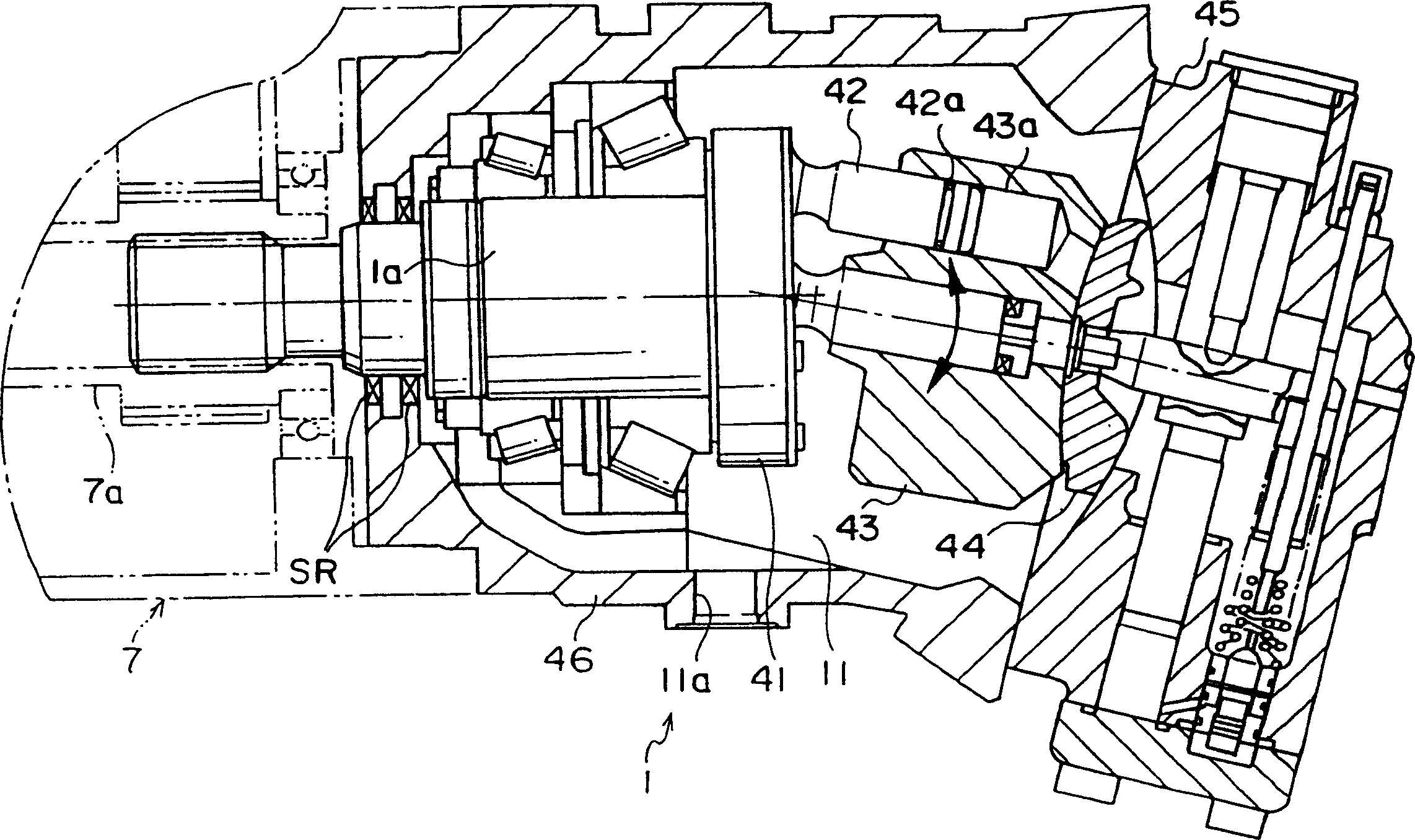
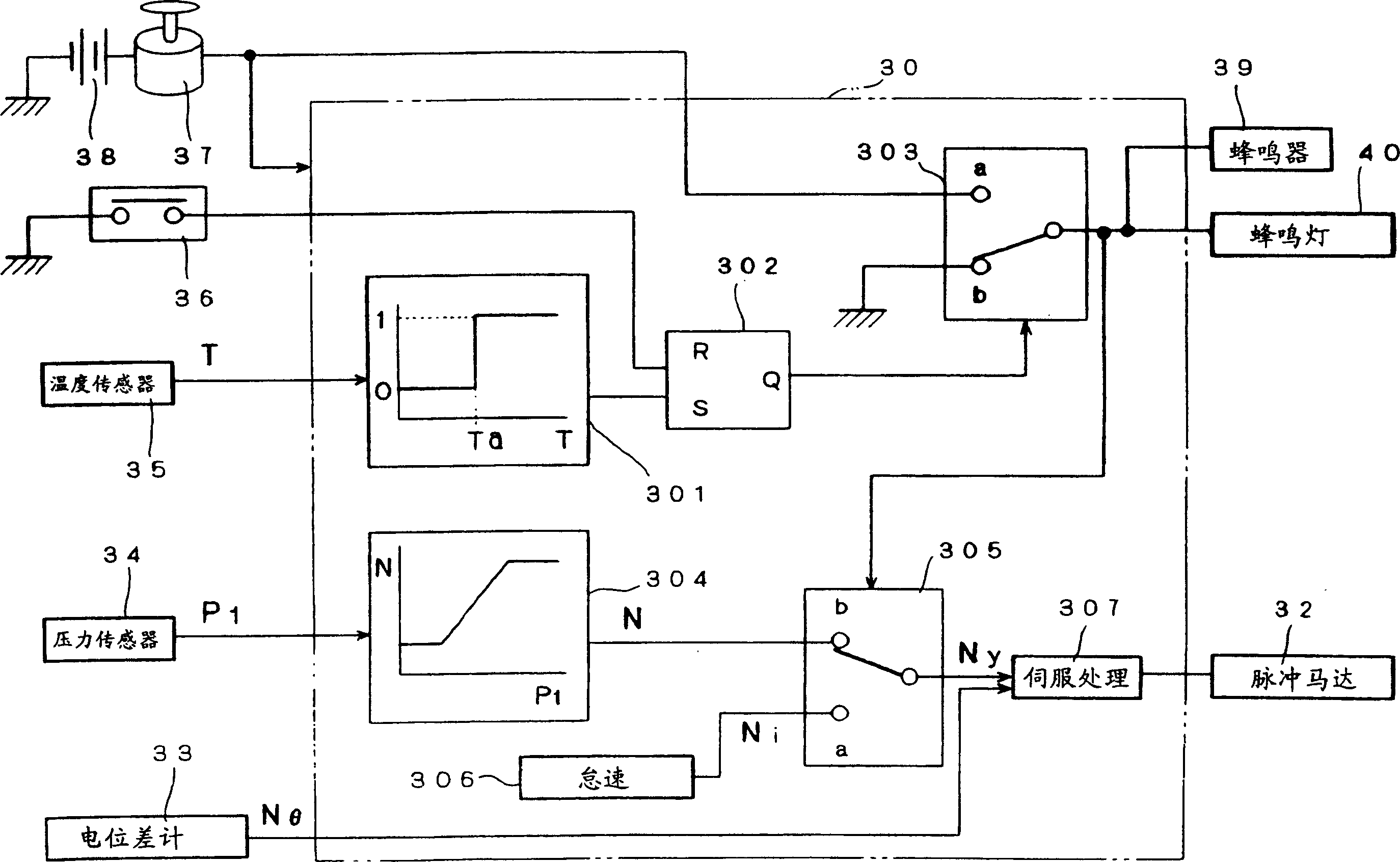
[0057] When the traveling motor 1 rotates at a high speed, the frictional force of the sliding part of the piston 42 increases, the piston 42 is sintered, and the traveling motor 1 may be damaged. Therefore, in the second embodiment, when the rotation speed of the travel motor 1 increases to more than the predetermined value Na, a sign of failure of the travel motor 1 is detected. Below, according to Figure 5 , 6 A second embodiment of the present invention will be described. Figure 5 It is a circuit diagram showing the structure of a wheeled hydraulic excavator equipped with a failure detection device according to a second embodiment. Image 6 It is a schematic diagram illustrating the controller 30A of the second embodiment in detail. In addition, in the same figure 1 , 3 The same parts are given the same reference numerals, and the differences will be mainly described below.
[0058] Such as Figure 5 As shown, a rotational speed sensor 26 for detecting the rotatio...
no. 3 approach
[0061] In the third embodiment, a precursor to failure of the travel motor 1 is detected when cavitation occurs. Below, according to Figure 7 , 8 A third embodiment of the present invention will be described. Figure 7 is a circuit diagram showing the structure of a wheeled hydraulic excavator equipped with a failure detection device according to a third embodiment, Figure 8 It is a schematic diagram showing the structure of the controller 30B of the third embodiment. Also, for figure 1, 3 The same reference numerals are assigned to the same parts, and the differences will be mainly described below.
[0062] Such as Figure 7 As shown, pressure sensors 27-29 are arranged on the inlet and outlet ports of the travel motor 1 and the supplementary port 13, and the motor inlet pressures during forward rotation, reverse rotation and braking of the motor are detected by these pressure sensors 27-29. Such as Figure 8 As shown, the function generators 322-324 output a high p...
PUM
 Abstract
Description
Claims
Application Information
 - R&D
- Intellectual Property
- Life Sciences
- Materials
- Tech Scout
- Unparalleled Data Quality
- Higher Quality Content
- 60% Fewer Hallucinations
Browse by: Latest US Patents, China's latest patents, Technical Efficacy Thesaurus, Application Domain, Technology Topic, Popular Technical Reports.
© 2025 PatSnap. All rights reserved.Legal|Privacy policy|Modern Slavery Act Transparency Statement|Sitemap|About US| Contact US: help@patsnap.com