Supercharge Your Innovation With Domain-Expert AI Agents!

Rotor unit for electromotor and internal rotor electromotor

An inner rotor and electric motor technology, applied in the field of rotor components for electric motors and inner rotor motors, can solve the problems of impossibility, loss, and non-direct generation

Inactive Publication Date: 2006-02-08
MINEBEA CO LTD
View PDF5 Cites 0 Cited by
  • Summary
  • Abstract
  • Description
  • Claims
  • Application Information

AI Technical Summary

Problems solved by technology

[0004] The problem that arises during the manufacture of such internal rotor motors is that when the rotor assembly is inserted into the inner space of the stator, ferromagnetic particles are carried away from the rotor magnets, which particles can reach the outer contour and stator which are substantially formed by the rotor magnets. The working clearance defined by the inner contour of the
[0009] The inner rotor motor of DE3237196 also has the disadvantage that, due to the sealing of the rotor assembly, direct mechanical coupling of the load is not possible, the torque transmitted from the rotor to the shaft can only be generated indirectly from the rotor to the shaft, e.g. by means of a magnetic coupling, as in described in the patent literature
However, additional parts are required, especially the sleeves thus "lost"

Method used


Image

  • Rotor unit for electromotor and internal rotor electromotor
  • Rotor unit for electromotor and internal rotor electromotor
  • Rotor unit for electromotor and internal rotor electromotor

Examples


Embodiment Construction

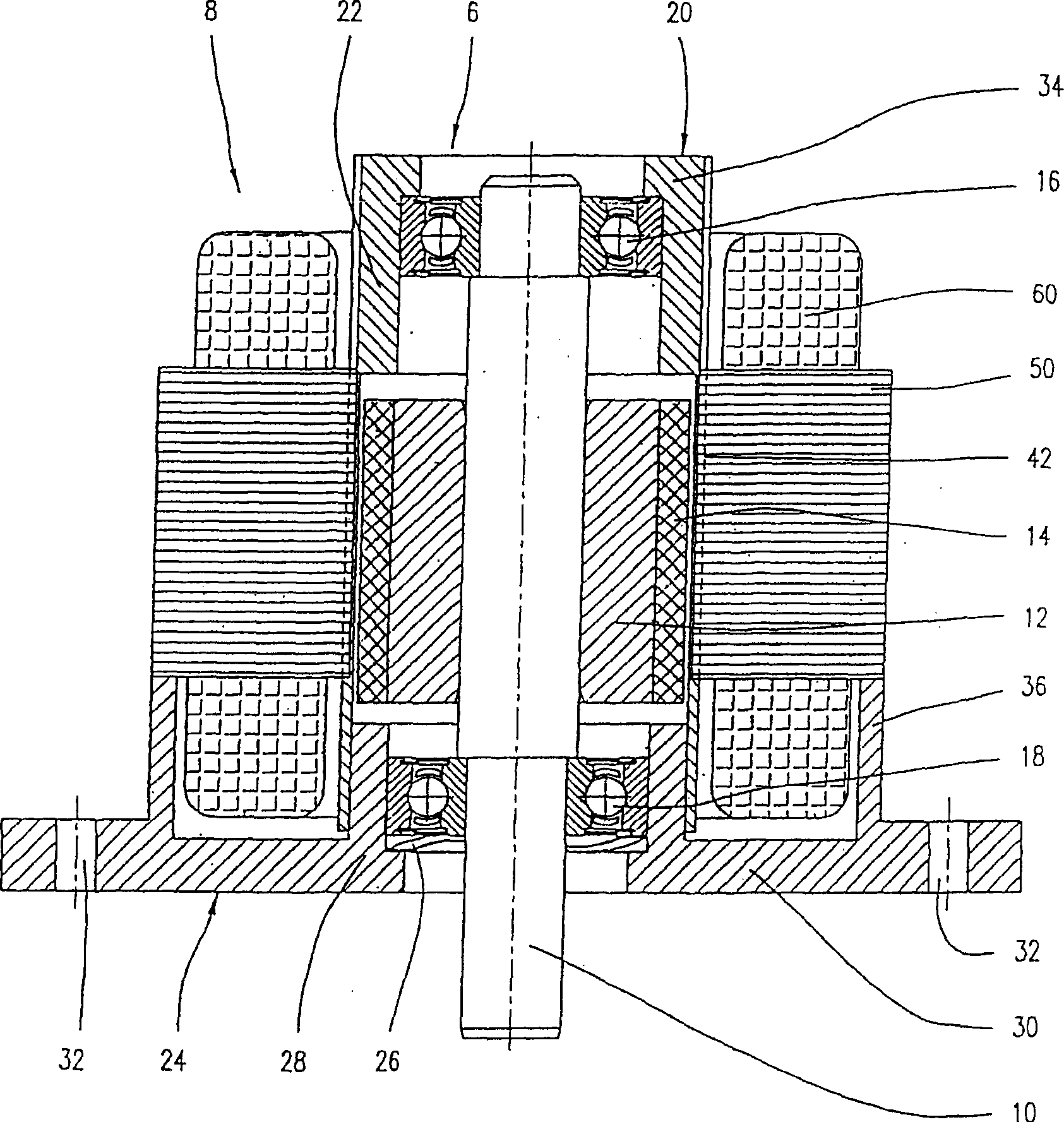
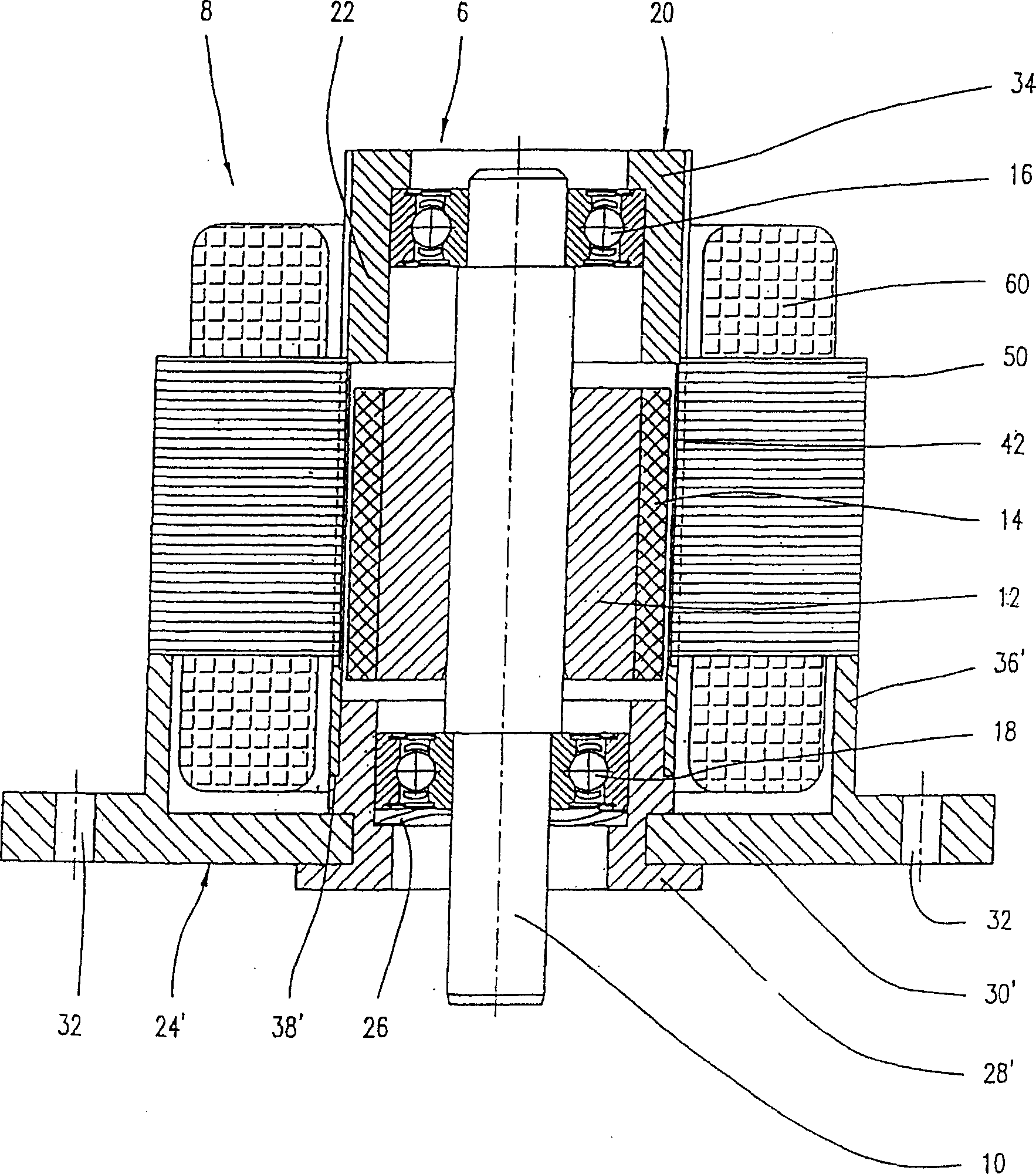
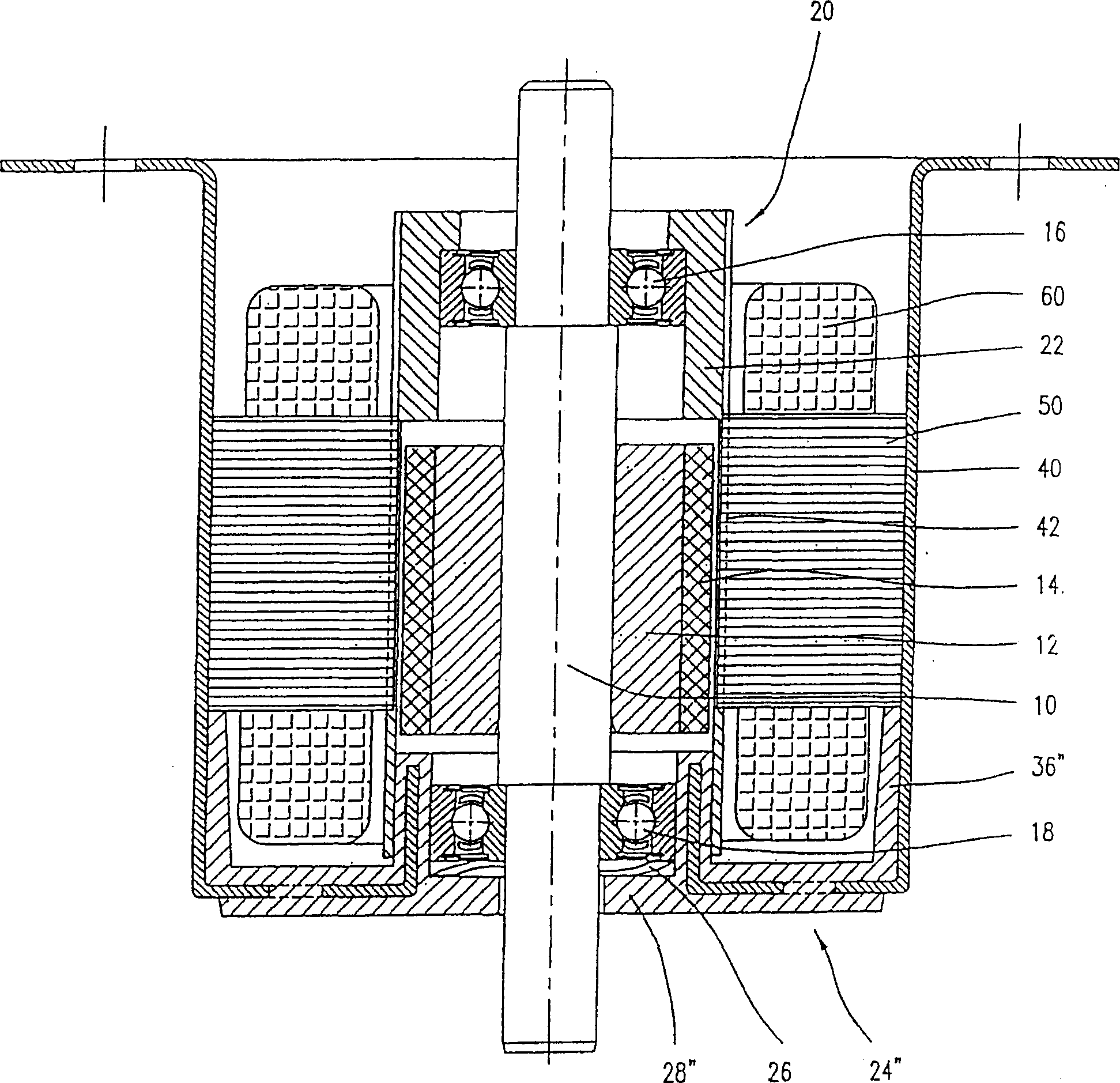
[0036] figure 1 A first embodiment of an electric motor according to the invention is shown, more specifically an inner rotor direct current motor. The electric motor includes a rotor assembly 6 and a stator 8 . The rotor assembly has a rotor shaft 10 supported by a back iron ring 12 of soft magnetic material such as steel. A segmented or annular permanent magnet 14 is attached to the back iron ring 12 . The shaft 10 is rotatable within bearings 16, 18, which are formed as needle bearings or friction bearings, more particularly ball bearings. The rotor comprising rotor shaft 10 , back iron ring 12 and one or more permanent magnets 14 is enclosed within a sleeve 20 comprising a cup portion 22 and a flange 24 . exist figure 1 In the illustrated embodiment, the flange is fabricated from a piece comprising a central cover portion 28 and a flange portion 30 . The flange portion 30 has holes 32 distributed over the periphery of the motor. In the illustrated embodiment, the cup...


PUM


Abstract

The invention relates to a rotor unit for an electromotor, comprising a rotor shaft and at least one permanent magnet arranged thereon. Said rotor shaft comprising a permanent magnet is housed in a bushing and is freely rotatable therein. The bushing is closed on a first end thereof by a flange. The invention also relates to an internal rotor electromotor comprising a stator and a rotor unit in the above-mentioned form, the stator being pushed onto the bushing in the rotor unit.

Description

technical field [0001] The invention relates to a rotor assembly for an electric motor and an inner rotor electric motor using such a rotor assembly, said rotor assembly comprising a rotor shaft and at least one permanent magnet arranged on the rotor shaft. Background technique [0002] The present invention relates to the field of brushless electric motors with permanent magnets, and more particularly to direct current electric motors configured as so-called inner rotor motors. An inner rotor electric motor includes a rotor assembly including a rotor shaft and one or more permanent magnets disposed on the rotor shaft, the rotor shaft being inserted into a stator assembly including a stator body and field coils. [0003] The construction of such a motor is described in US Patent No. 5,970,600. The electric motor includes a housing housing a stator, a rotor assembly, and bearings rotatably supporting the rotor assembly. The stator includes stator plates and coils, and defin...

Claims


Application Information

Patent Timeline
Patent Type & Authority Patents(China)
IPC IPC(8): H02K5/128H02K5/04H02K5/173H02K21/14
CPCH02K5/128H02K5/1732H02K1/27
Inventor 哈拉尔德·拉普奥斯瓦尔德·库沃特于尔根·奥尔施
Owner MINEBEA CO LTD
Features
  • R&D
  • Intellectual Property
  • Life Sciences
  • Materials
  • Tech Scout
  • Unparalleled Data Quality
  • Higher Quality Content
  • 60% Fewer Hallucinations
Learn More