Pipe pump
A technology of tube pumps and tubes, applied in the field of tube pumps, can solve problems such as difficulty in miniaturization, difficulty in thinning, and inability to store for a long time, and achieve the effects of miniaturization, long life and miniaturization
- Summary
- Abstract
- Description
- Claims
- Application Information
AI Technical Summary
Problems solved by technology
Method used
Image

Examples
no. 1 Embodiment approach
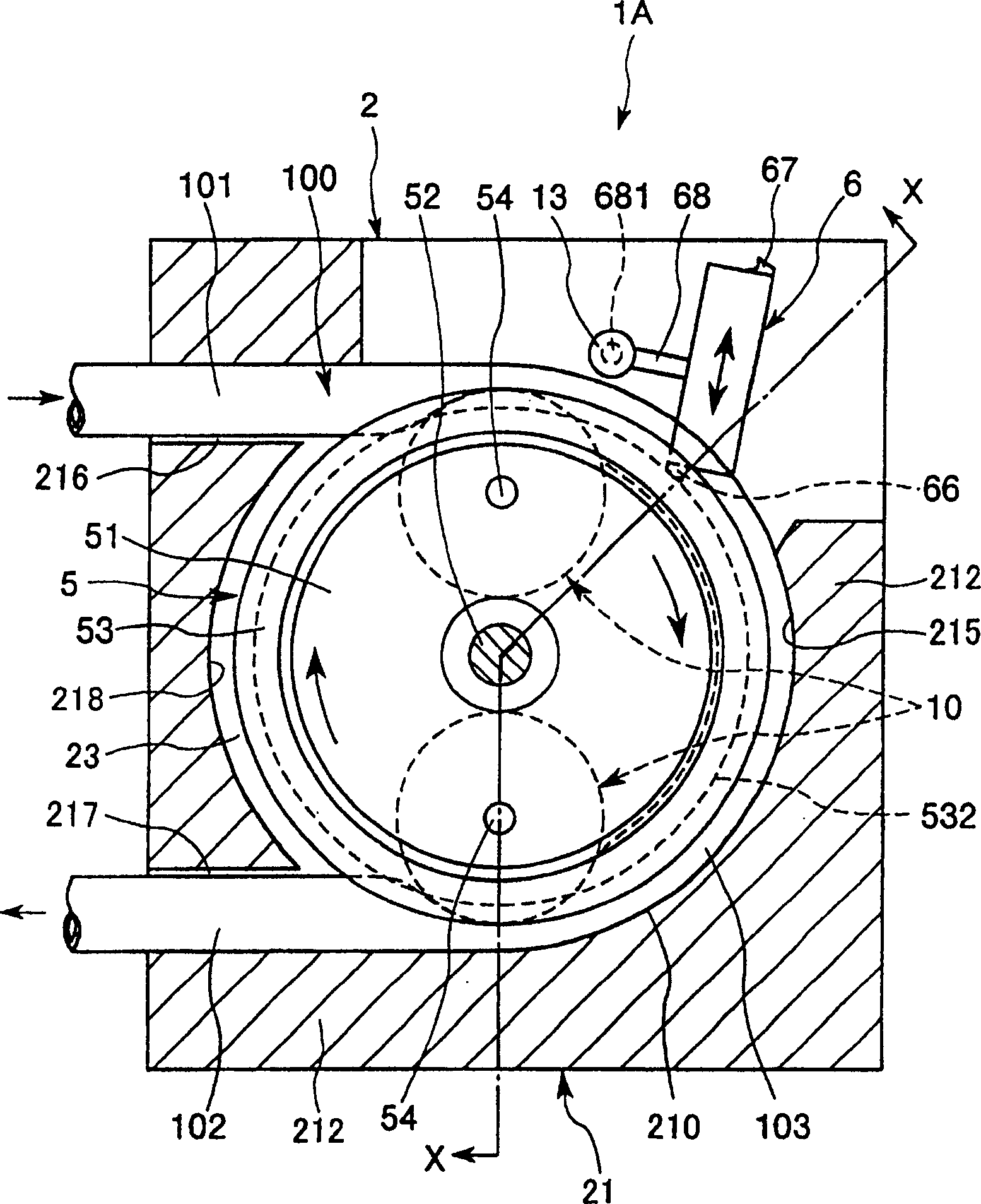
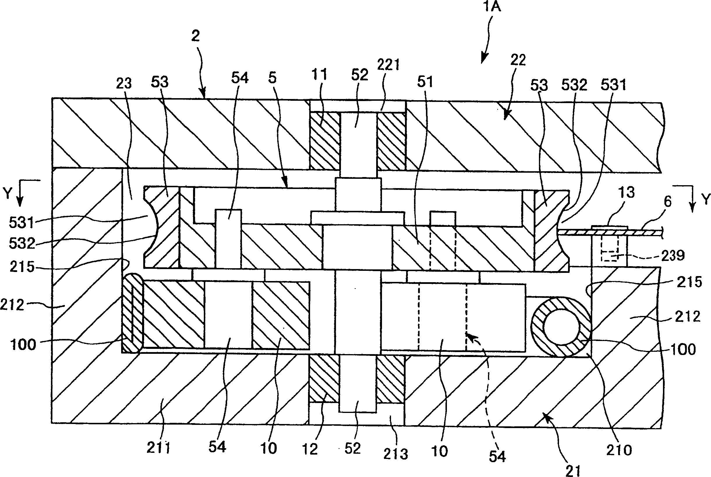
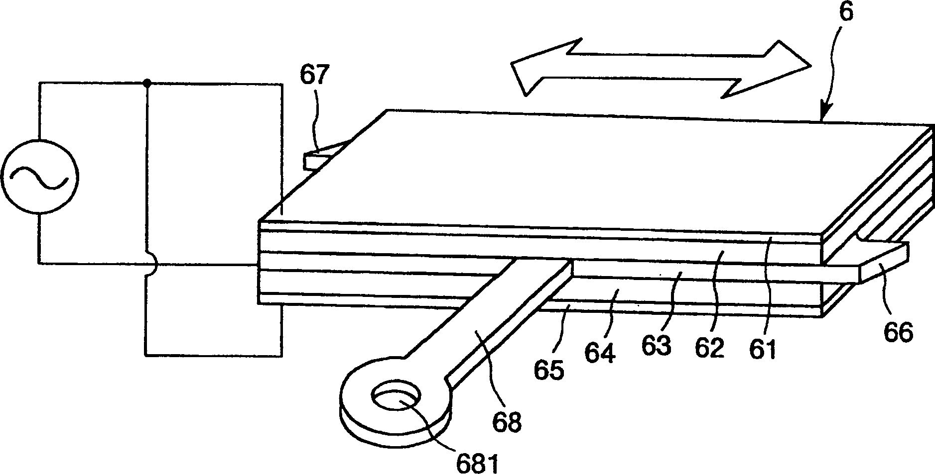
[0130] figure 1 and figure 2 are a sectional plan view and a sectional side view showing the first embodiment of the tube pump of the present invention, respectively, image 3 for figure 1 and figure 2 A perspective view of the vibrating body in the tube pump shown in, Figure 4 for figure 1 and figure 2 The top view of the vibrating body during bending vibration in the tube pump shown in , Figure 5 for figure 1 and figure 2 The top view of the convex part of the vibrating body in the tube pump shown in , when it performs elliptical motion. in addition, figure 1 for figure 2 The cross-sectional view at the Y-Y line in the center, figure 2 for figure 1 Sectional view at X-X line. Also, in the following description, the figure 2 The upper side in is called "upper", and the lower side is called "lower".
[0131] figure 1 and figure 2 The tube pump 1A shown in the figure includes: a main body 2 with a mounting portion 210 for installing an elastic tube 10...
no. 2 Embodiment approach
[0184] Figure 6 It is a sectional side view showing the second embodiment of the tube pump of the present invention. Also, in the following description, the Figure 6 The upper side in is called "upper", and the lower side is called "lower".
[0185] Hereinafter, a second embodiment of the tube pump according to the present invention will be described with reference to this figure, and the description will focus on the differences from the above-mentioned first embodiment, and the same description will be omitted.
[0186] In the tube pump 1B of this embodiment, the diameter of the drum 10 is smaller than that of the tube pump 1A of the first embodiment described above, and at the same time, it is displaced on the inner peripheral side of the rotor 5 .
[0187] Correspondingly, the shape of the base 21 is also different, and the radius of curvature of the inner peripheral surface 215 is reduced. That is, a step 214 is formed on the wall portion 212 , and the diameter of th...
no. 3 Embodiment approach
[0192] Figure 7 It is a plan view showing the third embodiment of the tube pump of the present invention, Figure 8 for Figure 7 Side view of the tube pump shown in . Also, in the following description, the Figure 8 The upper side in is called "upper", and the lower side is called "lower".
[0193] Hereinafter, a third embodiment of a tube pump according to the present invention will be described with reference to the drawings. The description will focus on differences from the first embodiment described above, and similar descriptions will be omitted.
[0194] In the tube pump 1C of the present embodiment, the vibrator 6 is provided so as to abut against the rotor main body 51 of the rotor 5 from the direction of the rotor rotating shaft 52 to drive the rotor main body 51 . That is, in this embodiment, the rotor main body 51 is a driven body, and the ring 53 is not provided on the rotor 5 .
[0195] The arm portion 68 of the driving body 6 is fixedly connected to the...
PUM
 Abstract
Description
Claims
Application Information
 - R&D
- Intellectual Property
- Life Sciences
- Materials
- Tech Scout
- Unparalleled Data Quality
- Higher Quality Content
- 60% Fewer Hallucinations
Browse by: Latest US Patents, China's latest patents, Technical Efficacy Thesaurus, Application Domain, Technology Topic, Popular Technical Reports.
© 2025 PatSnap. All rights reserved.Legal|Privacy policy|Modern Slavery Act Transparency Statement|Sitemap|About US| Contact US: help@patsnap.com