Unlock instant, AI-driven research and patent intelligence for your innovation.

Hall position sensor

A Hall position and sensor technology, which is applied in the use of electric/magnetic devices to transmit the direction of sensing components, instruments, measuring devices, etc., can solve the problems of the limitation of the detection range of the Hall position sensor, the reduction of system costs, and the disadvantages.

Inactive Publication Date: 2007-01-03
SHANGHAI POWERMAX TECH INC
View PDF10 Cites 0 Cited by
  • Summary
  • Abstract
  • Description
  • Claims
  • Application Information

AI Technical Summary

Problems solved by technology

Usually, the width of the Hall element is narrow, so the detection range of the Hall position sensor with this structure is greatly limited
[0008] In addition, in the Hall position sensor of this structure, the relative position x of the permanent magnet 1 is linearly related to the output voltage V(x) of the Hall element 2, but in some applications (such as for sewing machine pedals or The position sensor of the automobile accelerator pedal), the relative position x of the permanent magnet 1 and the output voltage V(x) of the Hall element 2 may have a better non-linear relationship. For this reason, a conversion process must be added, and the Hall The voltage linear output value is converted to other values, so as to realize the nonlinear relationship between the output voltage and the relative position, which increases the processing burden and complexity of the application system, and is not conducive to reducing the cost of the system

Method used


Image

  • Hall position sensor
  • Hall position sensor
  • Hall position sensor

Examples


Embodiment Construction

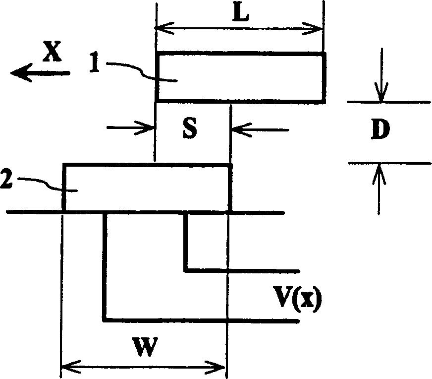
[0024] In the Hall position sensor of the above-mentioned prior art, since the air gap length D and the magnetic field strength B of the permanent magnet are constant, only the area S of the overlapping part of the surface of the permanent magnet and the Hall element increases with the relative increase of the permanent magnet and the Hall element. Changes in position, thus limiting the detection range of the sensor. The core idea of ​​the present invention is to make the change of the output voltage of the Hall element also related to the change of the shape of the air gap (that is, the spatial distribution of the length of the air gap in the overlapping part), so when the overlapping area S cannot represent the relative position change, the air gap can still be used It can be characterized by the shape, thereby expanding the variation range of the relative position. It should be understood that, in the present invention, the variation of the overlapping area and the variation...


PUM


Abstract

The Hall position sensor includes permanent magnet and Hall element, and the Hall element has its output voltage varying with the relative position variation of the permanent magnet. During the position variation, the area and / or air gap length of the superposed part between permanent magnet surface and Hall element surface are altered. So, the relative position variation includes the variation in the area of the superposed part and the variation in the air gap shape. In addition, by means of the proper relation of designed air gap shape, superposed area and output voltage, the relation between the required relative position and the output voltage of the Hall element may be obtained.

Description

technical field [0001] The invention relates to a magnetoelectric sensor, in particular to a Hall position sensor for measuring micro-displacement. Background technique [0002] Displacement or position sensors are an important class of basic sensors, including potentiometer, inductive, capacitive, eddy current and Hall sensors. The Hall-type displacement or position sensor has small inertia, high frequency response, reliable operation, and long life, so it is a commonly used displacement or position sensor. Its basic working principle is to keep the excitation current of the Hall element constant, and make the Hall element If there is a relative movement between the Hall element and the permanent magnet, there is a certain corresponding relationship between the displaced displacement or the relative position of the Hall element and the permanent magnet and the output Hall potential. Therefore, the relative position can be determined according to the output Hall potential. ...

Claims


Application Information

Patent Timeline
Patent Type & Authority Patents(China)
IPC IPC(8): G01D5/14G01B7/00G01B7/004
Inventor 徐性怡
Owner SHANGHAI POWERMAX TECH INC