Check patentability & draft patents in minutes with Patsnap Eureka AI!

Ink-jet recording head

An inkjet recording and discharge port technology, applied in printing and other directions, can solve the problems of increased fluid resistance at the discharge port, reduced ink droplet ejection speed, ink droplet ejection characteristics and image quality effects, etc.

Inactive Publication Date: 2007-01-24
CANON KK
View PDF8 Cites 0 Cited by
  • Summary
  • Abstract
  • Description
  • Claims
  • Application Information

AI Technical Summary

Problems solved by technology

However, this method has the following specific defects: since the heat generated by the electrothermal transducer is stored in the recording head, so that the volume of the moving ink droplet is changed, the cavitation phenomenon generated by the disappearance of the bubble is It can negatively affect the electrothermal transducer, and the air bubbles dissolved in the ink held in the recording head can also negatively affect the ejection characteristics of the ink droplets and the image quality
That is, when the ejection diameter is reduced in order to reduce the volume of ejected ink droplets, the fluid resistance of the discharge port will increase sharply, thereby reducing the flow rate to the discharge port and increasing the flow rate to the feed channel, which will reduce the ink flow rate. droplet ejection velocity

Method used


Image

  • Ink-jet recording head
  • Ink-jet recording head
  • Ink-jet recording head

Examples


no. 1 example

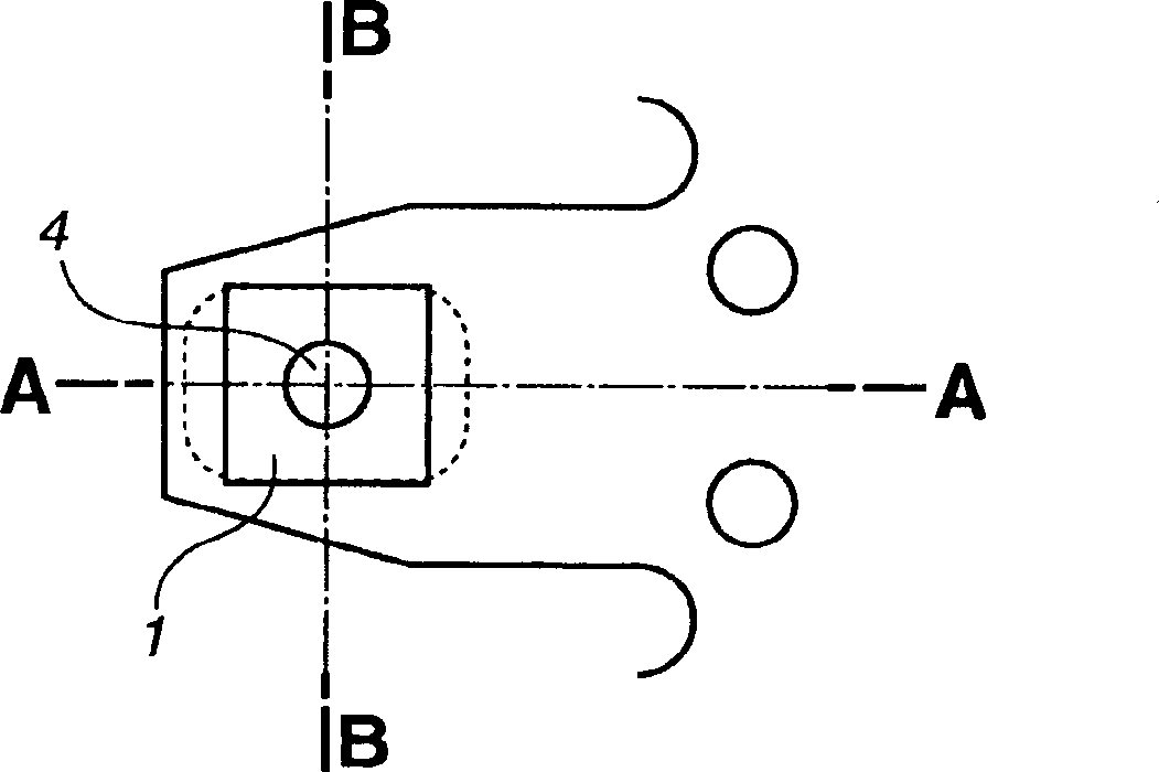
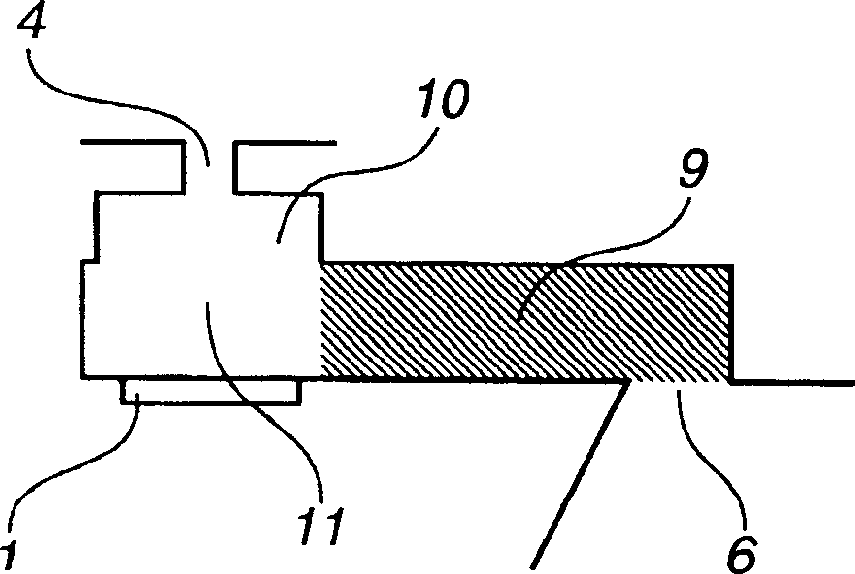
[0041] Figures 2A-2C The structure of the nozzles of the ink jet recording head according to the first embodiment of the present invention is shown. Figure 2A It is a plan perspective view in which, when viewed from a direction perpendicular to the main surface of the element substrate 2 (that is, the surface at the groove-shaped substrate to which the element substrate 2 is attached), a plurality of inkjet recording heads can be seen. one of the nozzles; Figure 2B for along Figure 2A The sectional view made by the section line A-A in ; Figure 2C for along Figure 2A Sectional view taken along section line B-B in .

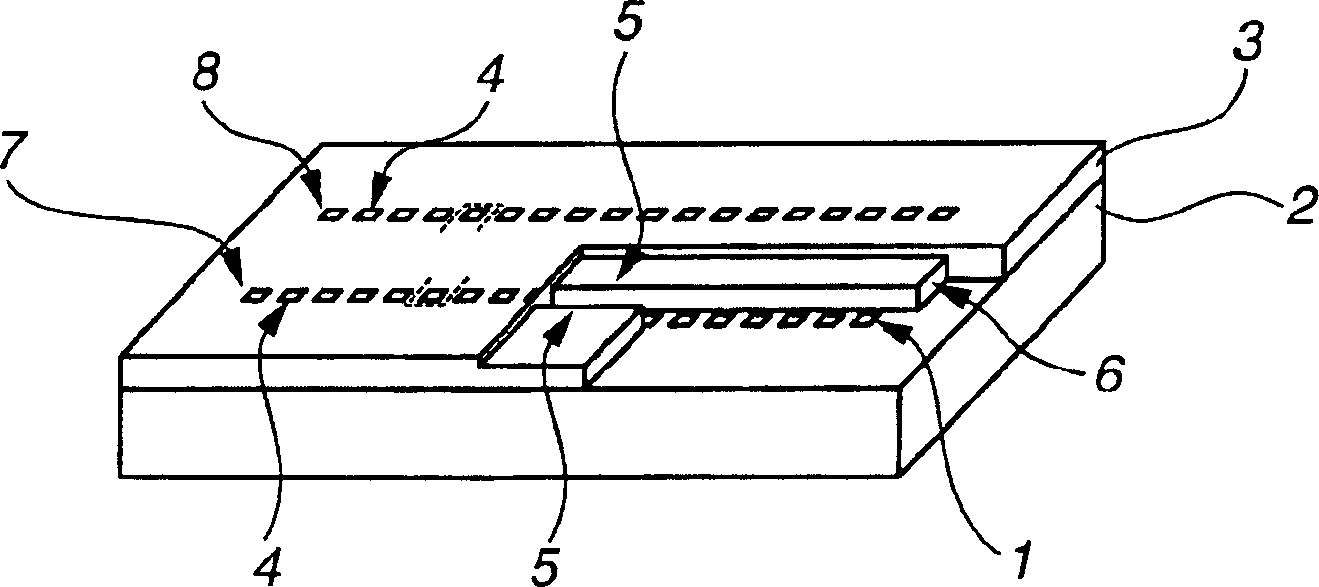
[0042] like figure 1 As shown, the recording head having the nozzle structure described in the first embodiment includes an element substrate 2, on which a plurality of heaters 1 and a groove substrate 3 are arranged, wherein each heater is used as an electrothermal transducer device, and the groove-shaped substrate constitutes a plurality of ink channe...

no. 2 example

[0052] In the second embodiment of the present invention, a nozzle having a structure in which the second discharge port portion is tapered in order to reduce stagnation of ink at the second discharge port portion is employed. The following will refer to Figures 3A-3C Parts different from the first embodiment will be mainly described.

[0053] Figures 3A-3C The nozzle structure of the inkjet recording head according to the second embodiment is shown. Figure 3A is a plan perspective view in which one of the plurality of nozzles of the inkjet recording head can be seen from a direction perpendicular to the main surface of the element substrate 2; Figure 3B for along Figure 3A Sectional view of section line A-A in; Figure 3C for along Figure 3A Sectional view of the middle section line B-B.

[0054] like Figures 3A to 3C As shown, as in the first embodiment, in the second embodiment of the ink jet recording head, the second discharge port portion 10 is provided wit...

no. 3 example

[0057] The object of the third embodiment of the present invention is to reduce the stagnation area of ​​the ink to reduce the variation of the discharge volume. In the second embodiment, the cross-section of the second discharge port portion is substantially rectangular. In this third embodiment, however, the cross-section of the second discharge port portion is elliptical.

[0058] The following will refer to Figures 4A to 4C , mainly explaining the parts of the third embodiment that are different from the first embodiment.

[0059] Figures 4A-4C The nozzle structure of the inkjet recording head according to the third embodiment is shown. Figure 4A is a plan perspective view in which one of the plurality of nozzles of the inkjet recording head can be seen from a direction perpendicular to the main surface of the element substrate 2; Figure 4B for along Figure 4A Sectional view of section line A-A in; Figure 4C for along Figure 4A Sectional view of the middle se...


PUM


Abstract

An ink-jet recording head according to the present invention includes a first discharge-port portion continuing from a discharge-port, and a second discharge-port portion for causing the first discharge-port portion to communicate with a bubble generation chamber. The second discharge-port portion has an end surface that includes a border portion with the first discharge-port portion and is parallel to a main surface of an element substrate. An area of a cross section of the second discharge-port portion that is parallel to the main surface of the element substrate is larger than an area of the border portion at any cross section of the second discharge-port portion from an opening surface facing the bubble generation chamber to an end surface facing the first discharge-port portion. A cross section of an opening surface of the second discharge-port portion facing the bubble generation chamber has a shape such that a length in a direction perpendicular to a direction of arrangement of the discharge-port is larger than a length in a direction parallel to the direction of arrangement of the discharge-ports . According to the ink-jet recoding head having the above-described configuration, it is possible to prevent a decrease in the discharge speed of an ink droplet due to reduction in the discharge diameter, without hindering high-density arrangement of the discharge-ports.

Description

technical field [0001] The present invention relates to a liquid ejection head for performing a recording operation on a recording medium by ejecting droplets of liquid such as ink or the like. Specifically, the present invention relates to a liquid ejection head for performing inkjet recording operations. Background technique [0002] The inkjet recording method is a so-called non-impact recording method. In this ink jet recording method, the noise generated during recording is very small, and a high-speed recording operation can be performed. In addition, recording can be performed on various recording media. For example, ink can be fixed on a so-called plain paper without special treatment, and very precise images can be obtained at low cost. Because of these characteristics, in recent years, this inkjet recording method has been quickly applied not only to printers as peripheral equipment for computers, but also as recording components for copiers, facsimile machines,...

Claims


Application Information

Patent Timeline
Patent Type & Authority Patents(China)
IPC IPC(8): B41J2/135
Inventor 富泽恵二村上修一
Owner CANON KK
Features
  • R&D
  • Intellectual Property
  • Life Sciences
  • Materials
  • Tech Scout
  • Unparalleled Data Quality
  • Higher Quality Content
  • 60% Fewer Hallucinations
Learn More