Check patentability & draft patents in minutes with Patsnap Eureka AI!

Switching power source circuit

A technology of switching power supply circuits and limiting circuits, which is applied in the direction of emergency protection circuit devices, electrical components, and adjusting electrical variables, etc., can solve problems such as inability to obtain power, decrease in peak drain current of power transistors, and inability to start, so as to reduce peak leakage The effect of polar current

Inactive Publication Date: 2007-08-22
SANYO ELECTRIC CO LTD
View PDF4 Cites 0 Cited by
  • Summary
  • Abstract
  • Description
  • Claims
  • Application Information

AI Technical Summary

Problems solved by technology

[0014] However, when the switching power supply is started, since there is no forward voltage excited by the drive winding of the pulse transformer initially, the peak current limiting circuit operates
As a result, the peak drain current of the power transistor is reduced, and the power in the normal state cannot be obtained, and it cannot be started.

Method used


Image

  • Switching power source circuit
  • Switching power source circuit
  • Switching power source circuit

Examples


Embodiment Construction

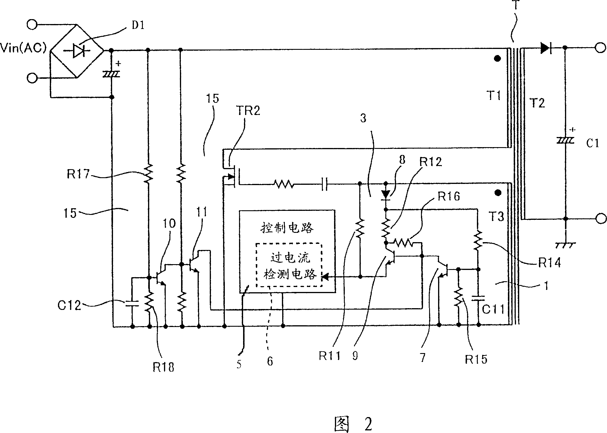
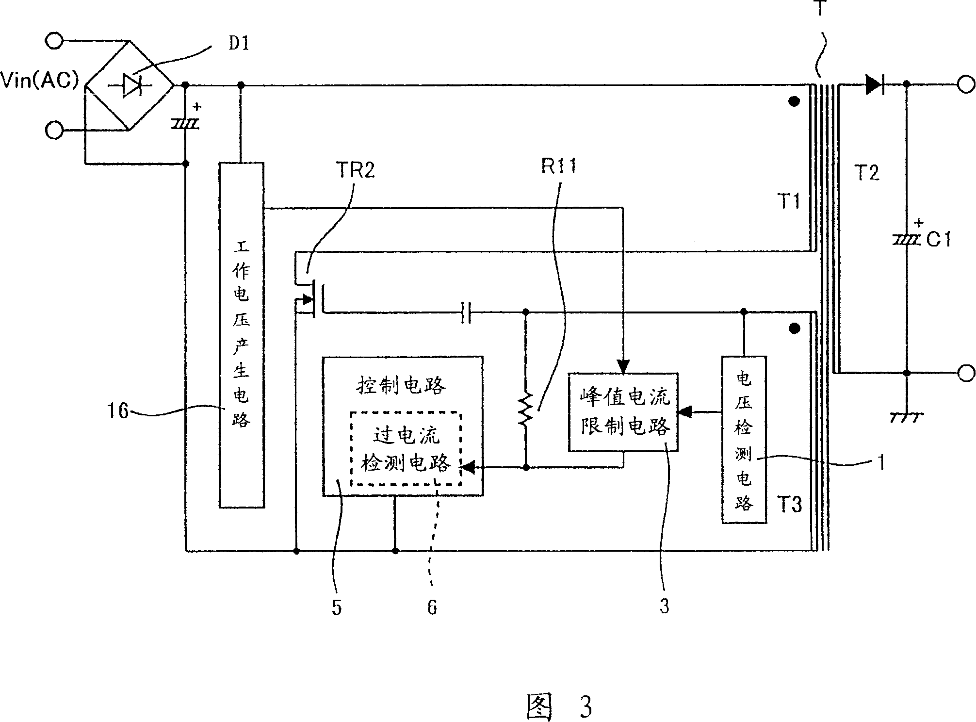
[0027] Embodiments of the present invention will be described in detail with reference to FIGS. 1-4 .

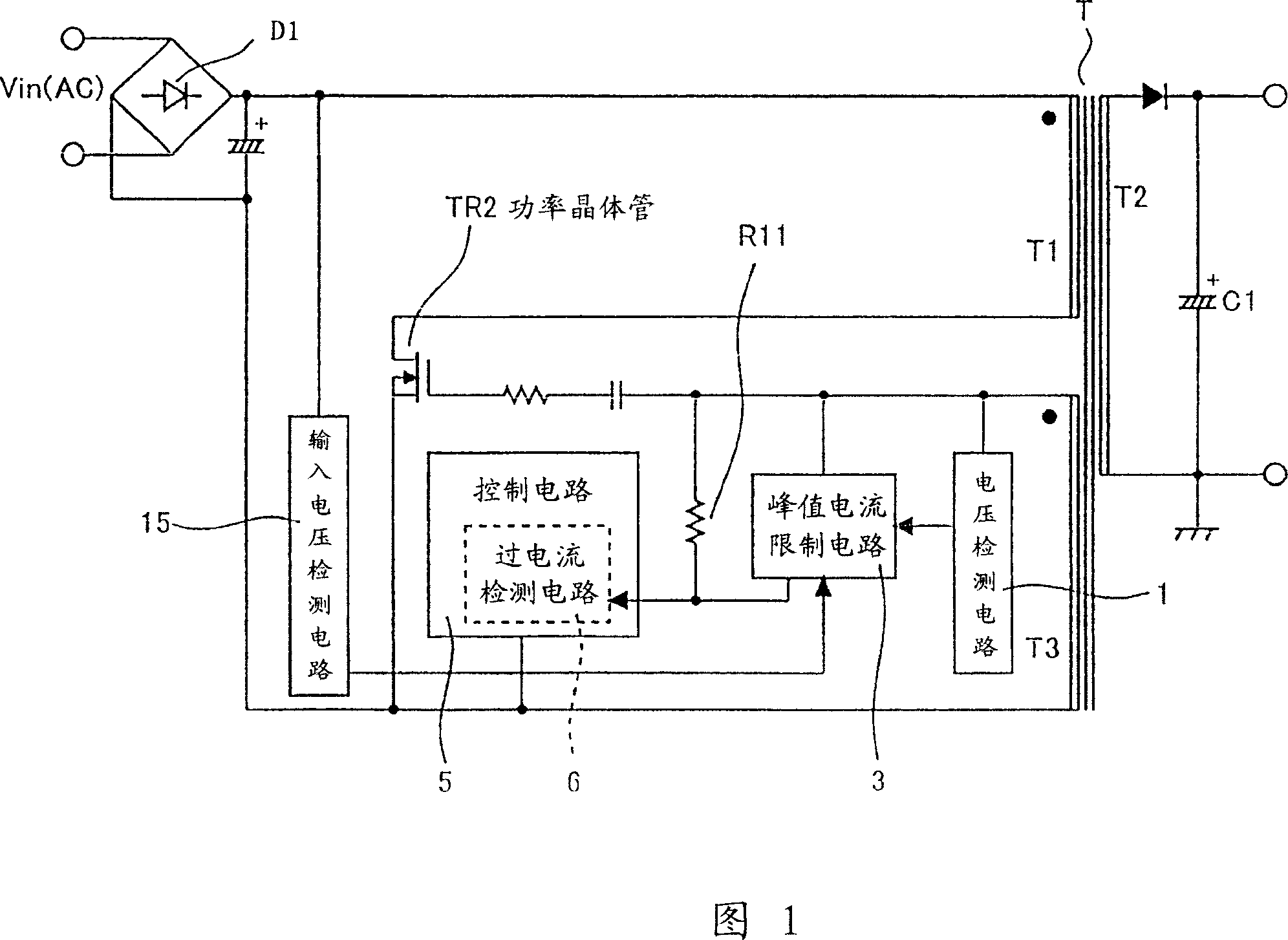
[0028] Fig. 1 is the switching power supply circuit of the present invention that prevents the abnormal sound from being heard during light-load intermittent oscillation and can start. The same structural parts as those in the prior art are denoted by the same symbols.

[0029] An AC voltage from an AC power source (not shown) on the primary winding T1 side of the pulse transformer T is applied to each component constituting the switching power supply circuit via a rectifier diode D1.

[0030] TR2 is a power transistor. The power transistor TR2 is turned on or off through the control signal, and then the voltage rectified by the rectifier diode D1 is converted and output to the secondary winding of the pulse transformer through the primary winding of the pulse transformer connected in series with the power transistor TR2. The resistor R11 It is a compensation resistor that ...


PUM


Abstract

Provided is a switching circuit capable of triggering with no trouble where an abnormal sound is prevented from occurring at intermittent oscillation. A voltage detecting circuit 1 detects decrease in a forward voltage which is induced at the drive coil T1 of a pulse transformer at intermittent oscillation. A peak current limit circuit 3 is operated when decrease in the forward voltage is detected at the voltage detecting circuit. An overcurrent detecting circuit 6 operates when the peak current limit circuit is operated to reduce the current flowing a power transistor. An input voltage detecting circuit 15 stops the peak current limit circuit during the period until it comes to be a normal state after a power supply is turned on.

Description

technical field [0001] The present invention relates to a switching power supply circuit equipped with a light-load intermittent oscillation corresponding circuit to realize low power consumption. Background technique [0002] As we all know, in the existing switching power supply circuit, especially in the RCC (ringing choke converter) power supply system, intermittent oscillation occurs at light load. However, in this intermittent oscillation state, 'Pi, Pi' and 'Bi, Bi' sounds are generated, which is called abnormal oscillation, and is regarded as an unacceptable state. However, this state has the effect of reducing power consumption loss, and it is very effective in realizing low power consumption of the circuit if it is used during standby or the like. However, since there is a problem of generating such an abnormal sound, it is not actually put into practical use. [0003] Therefore, if the above-mentioned circuit does not produce abnormal sound at light load and can...

Claims


Application Information

Patent Timeline
Patent Type & Authority Patents(China)
IPC IPC(8): H02M3/28H02H7/122H02M3/338
Inventor 斋藤孝昭西川円藤村芳夫
Owner SANYO ELECTRIC CO LTD
Features
  • R&D
  • Intellectual Property
  • Life Sciences
  • Materials
  • Tech Scout
  • Unparalleled Data Quality
  • Higher Quality Content
  • 60% Fewer Hallucinations
Learn More