Check patentability & draft patents in minutes with Patsnap Eureka AI!

Gain control amplified circuit and terminal equipment with the same gain control amplified circuit

A gain control and terminal equipment technology, applied in the direction of gain control, artificial gain control, amplification control, etc., can solve the problem of gain control amplifier non-control, and achieve the effect of easy realization and easy linear insertion into the circuit

Inactive Publication Date: 2002-02-13
NEC CORP
View PDF0 Cites 2 Cited by
  • Summary
  • Abstract
  • Description
  • Claims
  • Application Information

AI Technical Summary

Problems solved by technology

However, these gain-controlled amplifiers cannot be individually controlled individually

Method used


Image

  • Gain control amplified circuit and terminal equipment with the same gain control amplified circuit
  • Gain control amplified circuit and terminal equipment with the same gain control amplified circuit
  • Gain control amplified circuit and terminal equipment with the same gain control amplified circuit

Examples


Embodiment Construction

[0042] Preferred embodiments of the present invention will be described below with reference to the accompanying drawings.

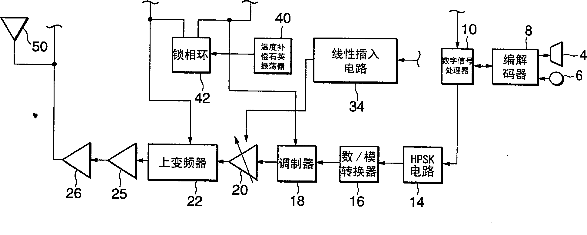
[0043] will refer to figure 2 The outline structure of the gain control amplifier circuit of the first embodiment of the present invention will be described.

[0044] figure 2 The circuit shown is that of a CDMA radio (terminal equipment) using a transmission / reception heterodyne scheme. First, the entire circuit arrangement of the terminal device will be described.

[0045] The antenna 50 is connected to a low noise amplifier 52 for amplifying the input received signal. The output of the low noise amplifier 52 is connected to a down converter 54 for converting the amplified received signal to an intermediate frequency (IF).

[0046] The output terminal of the down converter 54 is connected to a receiving section gain control amplifier (hereinafter referred to as RX gain control amplifier) ​​56 for amplifying the intermediate frequency signal outpu...


PUM


Abstract

A gain control amplification circuit of this invention has a gain control amplification section which has at least two stages and is arranged in the transmission circuit of a terminal equipment for communicating with a base station. The gain control amplification section includes gain control amplifiers of IF-GCA and RF-GCA arranged on the input side (former stage) and output side (latter stage) of an up converter in the transmission circuit. The gains of the gain control amplifiers are individually controlled by a control section.

Description

technical field [0001] The present invention relates to a gain control amplifying circuit, especially a wide range gain control amplifying circuit with multi-stage gain controlling amplifier capable of controlling the transmission output to a predetermined output value, and terminal equipment with the amplifying circuit. Background technique [0002] Modern radio communication requires high-speed communication and efficient use of frequency resources. For these purposes, Code Division Multiple Access (CDMA) systems have been used. In a CDMA system, data is multiplexed and transmitted to efficiently use the available frequency range. [0003] The CDMA system also needs to control the transmission power in a wide range to expand the communication area. [0004] figure 1 A conventional gain amplifier circuit is shown. In this conventional gain amplifier circuit, two gain amplifiers at the front stage and the rear stage are arranged before the antenna 50 to widen the transmi...

Claims


Application Information

Patent Timeline
Patent Type & Authority Applications(China)
IPC IPC(8): H03G3/20H03G3/02H03G3/30H04B1/04H04B1/3822H04B1/40
CPCH03G3/3052H03G3/3042
Inventor 长谷川修
Owner NEC CORP
Features
  • R&D
  • Intellectual Property
  • Life Sciences
  • Materials
  • Tech Scout
  • Unparalleled Data Quality
  • Higher Quality Content
  • 60% Fewer Hallucinations
Learn More