Supercharge Your Innovation With Domain-Expert AI Agents!

Optical sensor and high-frequency laminating module

An optical sensor, high-frequency technology, used in lasers, optical recording heads, laser parts, etc., can solve the problems of complex optical sensor configuration, etc.

Inactive Publication Date: 2002-10-02
TDK CORPARATION
View PDF1 Cites 3 Cited by
  • Summary
  • Abstract
  • Description
  • Claims
  • Application Information

AI Technical Summary

Problems solved by technology

This complicates the configuration of the optical sensor

Method used


Image

  • Optical sensor and high-frequency laminating module
  • Optical sensor and high-frequency laminating module
  • Optical sensor and high-frequency laminating module

Examples


Embodiment Construction

[0027] specific implementation plan

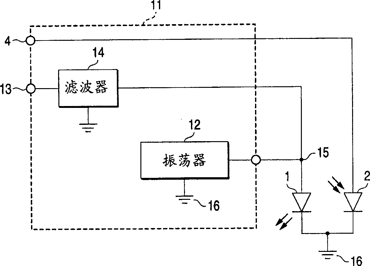
[0028] Figure 1A is a block diagram of an embodiment of a high frequency superposition module for an optical sensor according to the present invention. figure 2 yes Figure 1A circuit diagram. exist Figure 1A and figure 2 Among them, number 1 represents the laser diode used in the optical sensor, number 2 represents the photodetector diode, and number 11 represents the high-frequency superposition module. The number 4 represents the power supply terminal for the photodetector diode, the number 12 represents the oscillation circuit, the number 13 represents the power supply terminal for feeding direct current to the laser diode 1 and the power supply to the oscillation circuit 12, and the number 14 represents the power supply terminal used to prevent the oscillation circuit from 12 The high frequency generated is fed to the filter of the power supply.

[0029] The oscillation circuit 12 is connected between the junction 15 and the...


PUM


Abstract

A high-frequency superposition module for an optical sensor, which reduces the number of components, contributes to downsizing of the sensor, and enables an oscillation circuit when the power supply feeding a direct current to a laser diode is turned off and an optical sensor employs the high-frequency superposition module. closure. An oscillator circuit for feeding high frequency to a laser diode consists of at least one active component and several passive components such as capacitors, resistors and inductors. The power supply used to feed DC to the laser diode is also used as the power supply for this oscillation circuit.

Description

technical field [0001] The present invention relates to an optical sensor and a high frequency superimposing module provided in an information recording / reproducing apparatus using optical recording media such as DVD, MD, and CD. Background technique [0002] The laser diode as the laser source for the optical sensor is excited by a single mode during DC excitation. Single mode basically means that a single light output of a specific wavelength is obtained. However, when the laser diode is excited under single-mode conditions, the temperature rise of the laser diode will cause the center of the oscillation wavelength to gradually shift toward the longer wavelength at a certain wavelength interval. This variation of the oscillation wavelength is called mode popping, and the noise generated by the mode popping is called popping noise. In the case of a DVD employing a laser diode, the oscillation wavelength is 650 nm, and the mode interval is 0.1 nm. The onset wavelength of ...

Claims


Application Information

Patent Timeline
Patent Type & Authority Applications(China)
IPC IPC(8): G11B7/12G11B7/125G11B7/126H01S5/062
CPCG11B7/126H01S5/062
Inventor 田中正通
Owner TDK CORPARATION
Features
  • R&D
  • Intellectual Property
  • Life Sciences
  • Materials
  • Tech Scout
  • Unparalleled Data Quality
  • Higher Quality Content
  • 60% Fewer Hallucinations
Learn More