Supercharge Your Innovation With Domain-Expert AI Agents!

Cope holder device

A clamping device, the technology of the upper type, applied in the direction of forming tools, metal processing equipment, manufacturing tools, etc., can solve the problem of the upper type falling off

Inactive Publication Date: 2004-05-26
AMADA CO LTD
View PDF0 Cites 5 Cited by
  • Summary
  • Abstract
  • Description
  • Claims
  • Application Information

AI Technical Summary

Problems solved by technology

[0015] However, when replacing the upper type 107, depending on the situation, it is necessary to slide the upper type, and to apply an inestimable torsion force to the clamp. , even if it is not removed from the front or installed from the front, there is a danger that the upper mold will fall off

Method used


Image

  • Cope holder device
  • Cope holder device
  • Cope holder device

Examples


Embodiment Construction

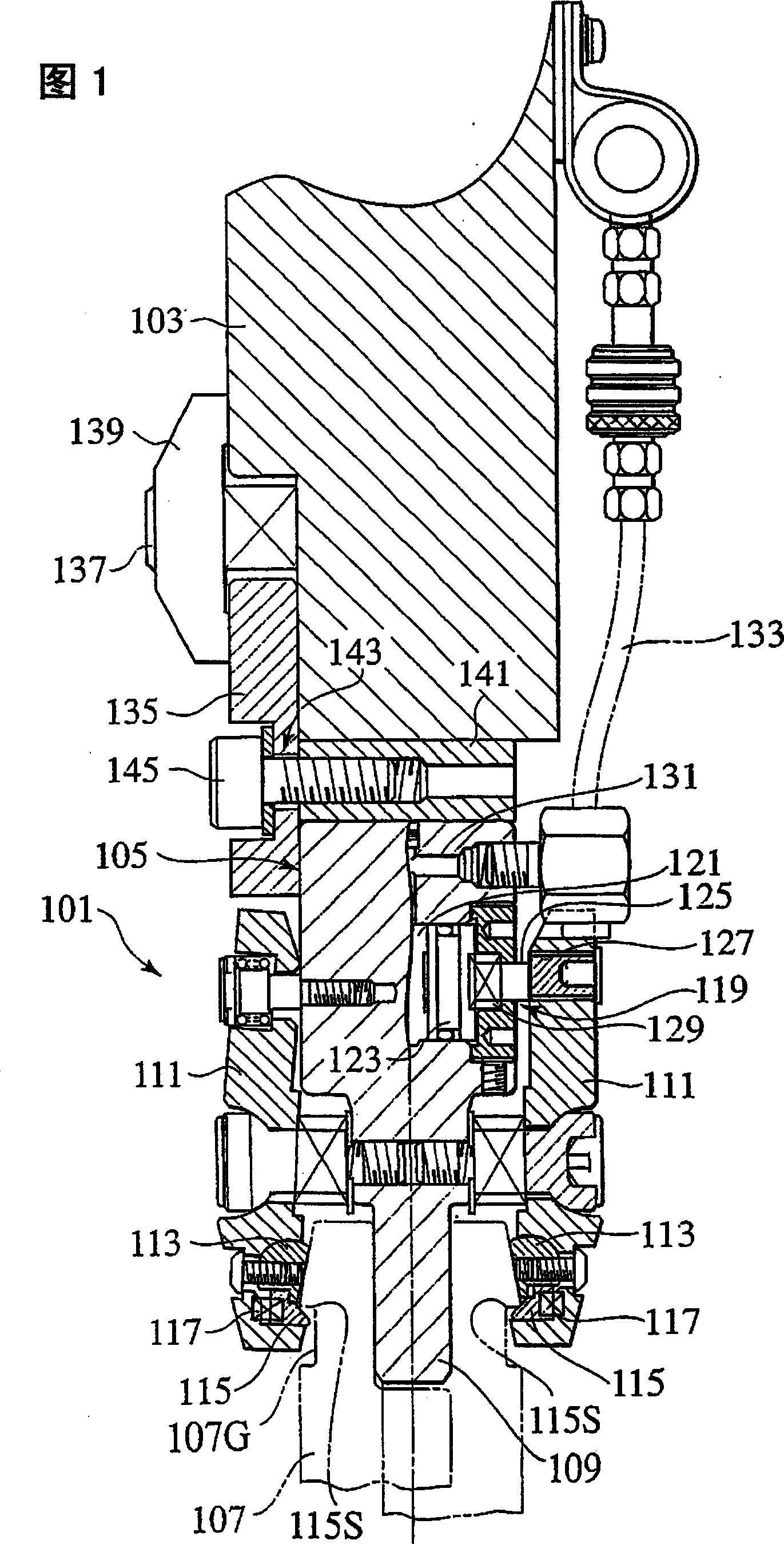
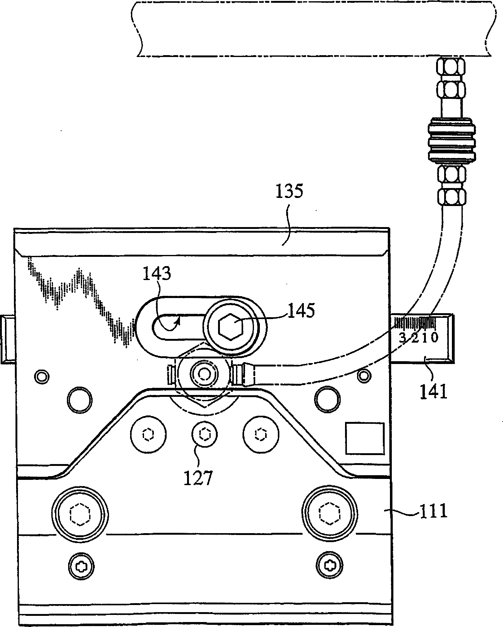
[0040] Hereinafter, the upper type clamping device and the method of removing the upper type clamping device from the upper type clamping device according to the present invention will be described with reference to the drawings.

[0041] As shown in Figure 5, Figure 6As shown, the upper type clamping device 1 of the present embodiment is detachably mounted on the lower part of the upper workbench 3 of the bending machine (not showing its overall composition in the figure). A plurality of the upper clamping devices 1 are installed at appropriate intervals in the left-right direction on the lower portion of the upper table 3 and used.

[0042] That is, the upper type 5 of the bending machine is along the left-right direction (in Fig. 5, the direction perpendicular to the plane of paper, Figure 6 The middle is the left and right direction) and its total length is integrated, and it is also used in combination of several split types of different sizes. Since the upper type cla...


PUM


Abstract

Upper die holder. An upper die supporting section for supporting an upper die is provided to a lower portion of a holder body (7), a pressing section for pressing the upper die against the upper die supporting section is provided to a lower portion of an upper die clamp (11) supported to the holder body (7) in a rocking manner with a vicinity of a center in a vertical direction being as a supporting point. A locking member which freely locks into a drop-proof groove provided to the upper die is provided to a lower portion of the upper die clamp (11), and it is biased towards the upper die supporting section. Clamping force applying means (13) for pressing an upper portion of the upper die clamp (11) so as to apply a clamping force for clamping the upper die using the upper die clamp (11) is provided. A pressure receiving member (59) which is pressed by the clamping force applying means (13) is provided to the upper portion of the upper die clamp (11) so that its advancing and retreating are freely adjusted and an opening quantity of the upper die clamp (11) at the time of unclamping is freely selected from a plurality of stages.

Description

technical field [0001] The present invention is related to the clamping device of the upper type of the bending machine, specifically, it is related to the clamping device of the upper type that can be easily disassembled and replaced on the upper workbench of the bending machine. Background technique [0002] In the prior art, the plate bending machine is composed of an upper workbench (also called an upper backing plate) and a lower workbench (also called a lower backing plate) arranged up and down oppositely, and the upper workbench or the lower workbench is placed on the suitable one. Make a pressure head that can be driven up and down. [0003] As can be seen from the above configuration, in order to process a plate-shaped workpiece, a lower die (die) is installed on the upper part of the lower table, and an upper die (punch) is installed on the lower part of the upper table in order to process the plate-shaped workpiece. [0004] In the above structure, after the work...

Claims


Application Information

Patent Timeline
Patent Type & Authority Applications(China)
IPC IPC(8): B21D37/14B21D5/02
CPCB21D5/0236B21D5/0209B21D5/02
Inventor 林史郎高桥祐纪川野敏郎
Owner AMADA CO LTD
Features
  • R&D
  • Intellectual Property
  • Life Sciences
  • Materials
  • Tech Scout
  • Unparalleled Data Quality
  • Higher Quality Content
  • 60% Fewer Hallucinations
Learn More