Supercharge Your Innovation With Domain-Expert AI Agents!

Charger and charging method

A charging device and charging current technology, which is applied in the direction of circuit devices, battery circuit devices, secondary battery charging/discharging, etc., can solve problems such as ineffective charging and long time required for charging completion

Inactive Publication Date: 2004-07-07
MAKITA CORP
View PDF1 Cites 11 Cited by
  • Summary
  • Abstract
  • Description
  • Claims
  • Application Information

AI Technical Summary

Problems solved by technology

[0005] The charging device described in the above-mentioned Patent Document 1 can suppress the temperature rise of the power supply circuit, but when the temperature of the power supply circuit rises, the supply of charging current to the battery is stopped, so the charging cannot be performed efficiently, and it takes a long time until the charging is completed.

Method used


Image

  • Charger and charging method
  • Charger and charging method
  • Charger and charging method

Examples


Embodiment Construction

[0023] Hereinafter, a charging device and a charging method according to an embodiment of the present invention will be described with reference to the drawings. The charging device is used to charge battery packs used in electric tools such as motorized wrench.

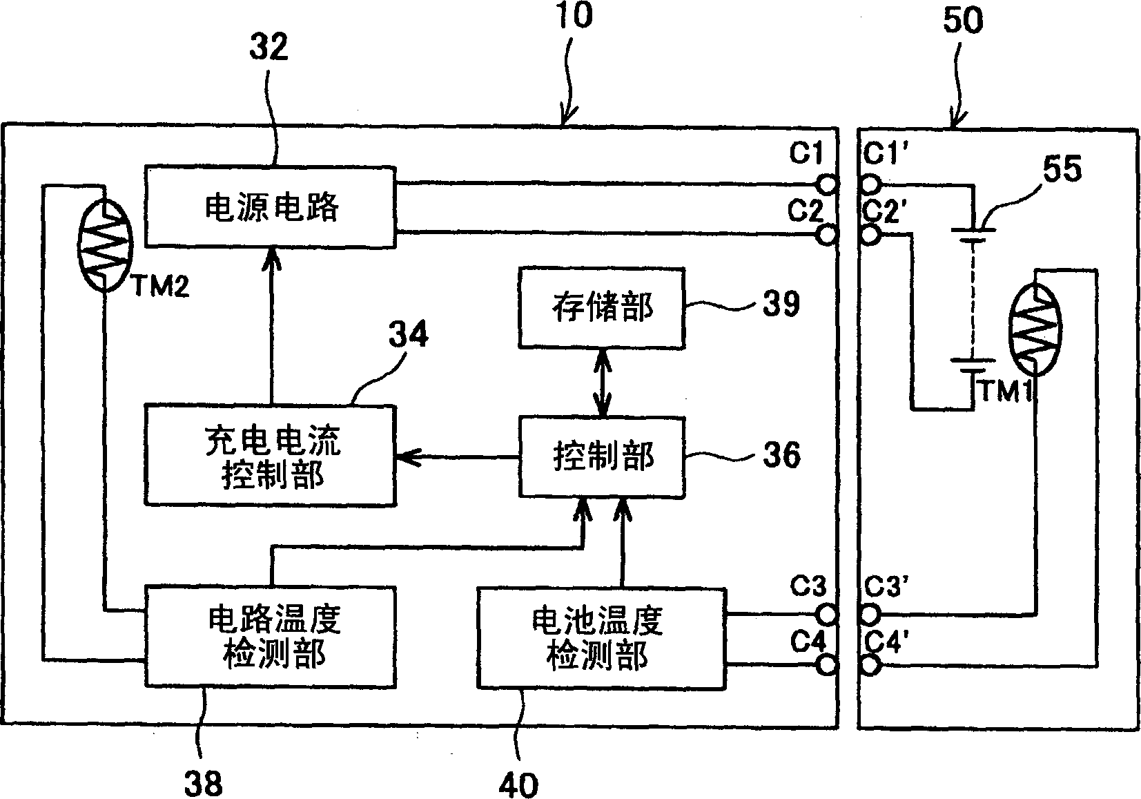
[0024] figure 1 It is a block diagram showing both the charging circuit of the charging device 10 and the battery pack 50 . From figure 1 It is clear that when the battery pack 50 is installed in the charging device 10, the connection terminals C1 to C4 on the charging device 10 side and the connection terminals C1' to C4' on the battery pack 50 side contact and are electrically connected. The battery pack 50 accommodates a nickel metal hydride battery 55 as a secondary battery and a temperature sensor (thermistor) TM1 for detecting the battery temperature in a case (casing), and connection terminals C1' to C4' are respectively provided on the surface of the case.

[0025] The charging circuit of the charging devi...


PUM


Abstract

Battery pack (50) may include rechargeable batteries (55) and first temperature sensor TM1 for detecting the temperature of batteries (55). Battery charger (10) may include power source circuit (32) for supplying charging current to batteries (55) of battery pack (50). Battery charger (10) may also include second temperature sensor TM2 located in the vicinity of power source circuit (32). Battery charger (10) may further include a processor for controlling power source circuit (32). The processor may select charging current that will be supplied by power source circuit (32) to batteries (55) based at least upon battery temperature from first temperature sensor TM1 and power source circuit temperature from second temperature sensor TM2, and supply the selected charging current to batteries (55).

Description

technical field [0001] The present invention relates to a charging device and a charging method for charging a battery (secondary storage battery). Background technique [0002] A secondary battery that can be recharged repeatedly is used as a power source for electric tools and the like. In order to perform continuous work for a long time using such an electric tool (rechargeable tool), it is necessary to replace the battery. Therefore, there is a method of use that prepares multiple batteries when working continuously for a long time, charges the other batteries that have been used up while one battery is in use, and when the battery in use becomes the state to be charged , replace it with another fully charged battery, and continue working. Therefore, in order to reduce the number of batteries to be prepared, it is necessary to charge the batteries in a short time. That is, it is necessary to increase the charging current supplied to the battery. However, when the cha...

Claims


Application Information

Patent Timeline
Patent Type & Authority Applications(China)
IPC IPC(8): H02J7/04H01M10/44H01M10/46H01M10/48H02J7/00H02J7/10
CPCH01M10/46H01M10/486H02J7/0091Y02E60/10H02J7/007194
Inventor 榊原和征
Owner MAKITA CORP
Features
  • R&D
  • Intellectual Property
  • Life Sciences
  • Materials
  • Tech Scout
  • Unparalleled Data Quality
  • Higher Quality Content
  • 60% Fewer Hallucinations
Learn More