A LED display device

A technology for display devices and LED arrays, applied in identification devices, static indicators, instruments, etc., can solve problems such as reverse current increase, and achieve the effect of eliminating power consumption

Inactive Publication Date: 2005-03-16
贺伟
View PDF1 Cites 5 Cited by
  • Summary
  • Abstract
  • Description
  • Claims
  • Application Information

AI Technical Summary

Problems solved by technology

[0005] First, to further improve the ZL01107628.3 medium and low power consumption LED display device, solve the power consumption problem caused by the reverse voltage when t

Method used


Image

  • A LED display device
  • A LED display device
  • A LED display device

Examples


Example Embodiment

[0035] Example one

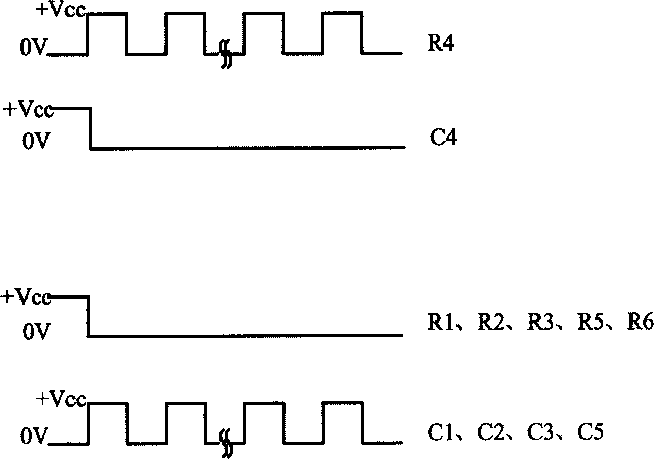
[0036] Provide alternating high and low pulse voltages at the P pole of the LED that needs to emit light, and provide a low level at its N pole. In order to prevent other LEDs from emitting light, a P pole that is connected to the light emitting LED must be provided at the N pole of the LED that does not need to emit light. Pulse voltages with the same pulse phase and pulse width are provided with a low level on its P pole.

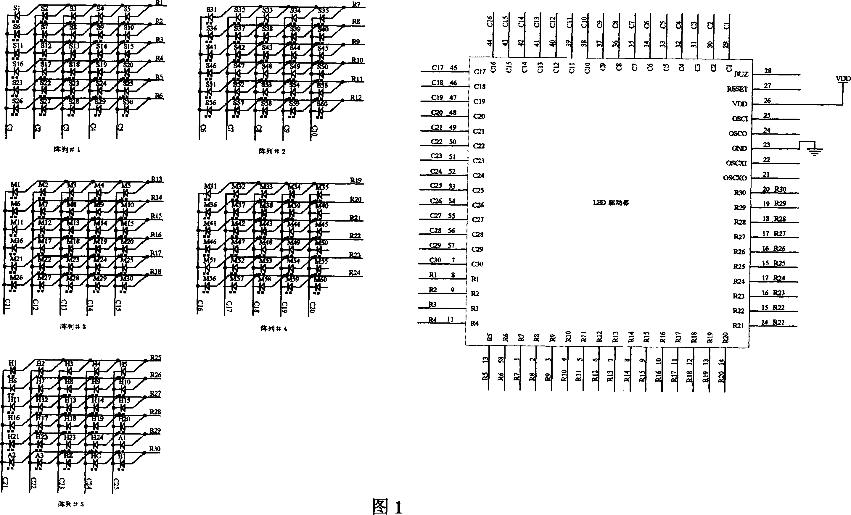
[0037] Such as figure 2 As shown, in the array #1, when the LED with the current number S19 emits light, the microprocessor outputs a pulse signal with adjustable pulse width to the row drive line R4 connected to its port, that is, a pulse signal with adjustable pulse width is applied to the P pole of S19. Adjust the pulse voltage of the pulse width, and at the same time the microprocessor outputs a low level to the column drive line C4 connected to the N pole of S19, so that the LED codenamed S19 is turned on and illuminated; at this ti...

Example Embodiment

[0066] Example two

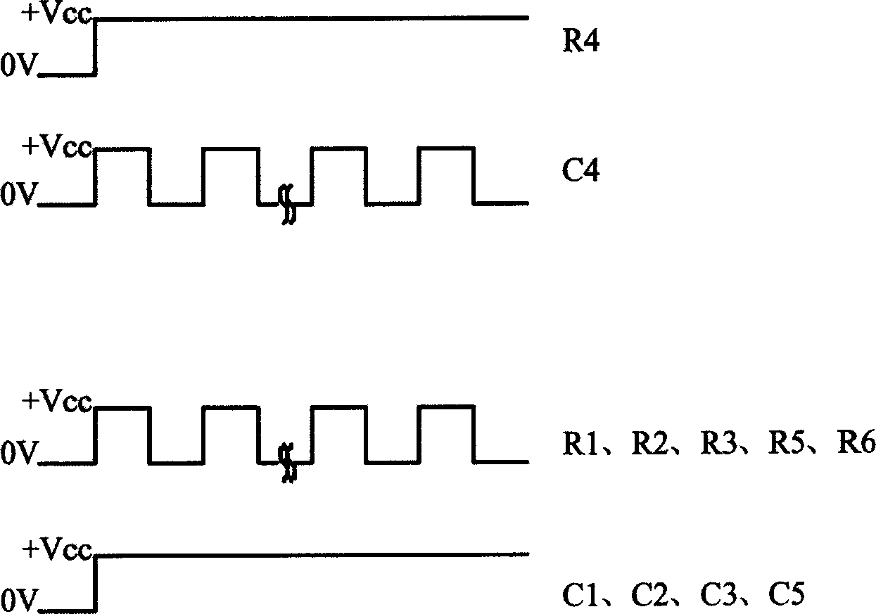
[0067] Provide a high level at the P pole of the LED that needs to emit light, and at the same time provide an alternating high and low pulse width pulse voltage at the N pole of the LED. In order to prevent other LEDs from emitting light, one must be applied to the N pole of the LED that does not need to emit light. High level, and at the same time provide a pulse voltage with the same phase and pulse width as the N-pole pulse of the light-emitting LED at its P pole.

[0068] Such as image 3 As shown, in array #1, when the LED with the current number S19 emits light, the microprocessor outputs a high level to the row drive line R4 connected to its port, that is, applies a high level to the P pole of S19, and at the same time The microprocessor outputs a pulse voltage signal with adjustable pulse width to the column drive line C4 connected to the N pole of S19, so that the LED codenamed S19 is turned on and displays light; at this time, in order to prevent oth...


PUM


Abstract

The invention relates to a LED display equipment, which resolves the power consumption problem caused by the reversed current generated by the reversed voltage when driving the LED array, with the synchronous pulse width impulse voltage. At the same time, the large-scale LED array is divided into several smaller scale ones, which can set the LEDs those needn't be turned on in the large-scale LED array to the static state mode. The invention resolves the power consumption problem effectively when the microprocessors or the application-specific integrated circuits drive the large scale LED array. Simultaneously, the problem that the reversed current boosts after the driving voltage has been raised can be solved.

Description

technical field [0001] The invention relates to an LED display device. Background technique [0002] In the existing LED display device, whether it is to use an ASIC or a microprocessor, there is a problem of reverse current power consumption generated by the reverse voltage when driving the LED array. Among them, in a Chinese Patent ZL01107628.3 discloses a low-power LED display device that can be applied to clocks and watches and other products. Compared with other existing technologies, when the driving voltage is below 2.4V and the wavelength is 550nm-635nm LED, the The driving structure has greatly improved the reduction of LED power consumption, but because this structure ignores the power consumption of the reverse current generated by the reverse voltage when driving a large-scale LED array, and when the driving wavelength is For 460-480nm blue or 520-530nm green LEDs, in order to obtain better brightness, the driving voltage must be increased to 3.4V. At this time,...

Claims


Application Information

Patent Timeline
IPC IPC(8): G09F9/33G09G3/14G09G3/32
Inventor 贺伟
Owner 贺伟
Why Eureka
Try Eureka