Accelerating decoder
A decoder, decoded technology, applied in other decoding technologies, error correction/detection by combining multiple code structures, digital transmission systems, etc.
- Summary
- Abstract
- Description
- Claims
- Application Information
AI Technical Summary
Problems solved by technology
Method used
Image

Examples
no. 1 example
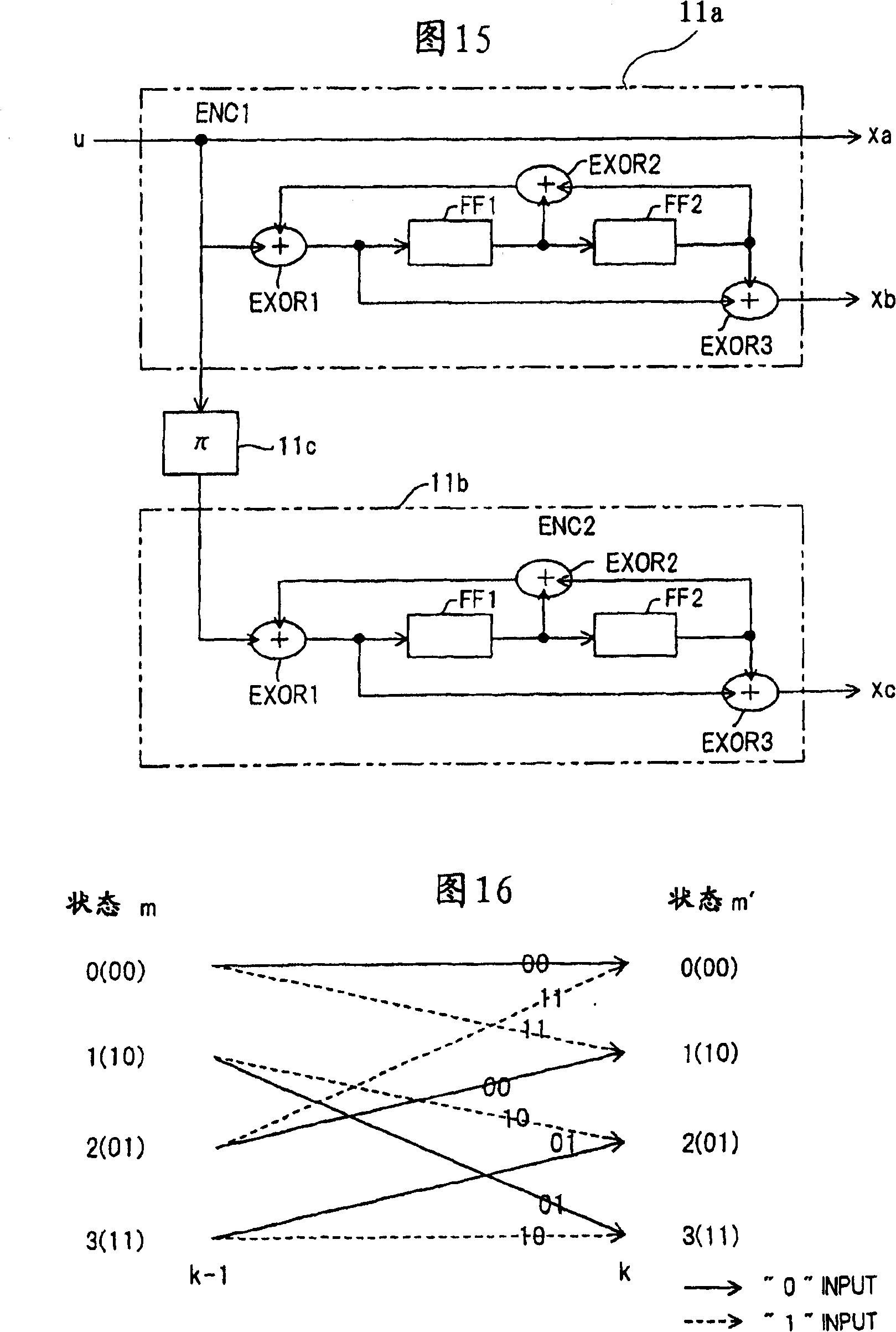
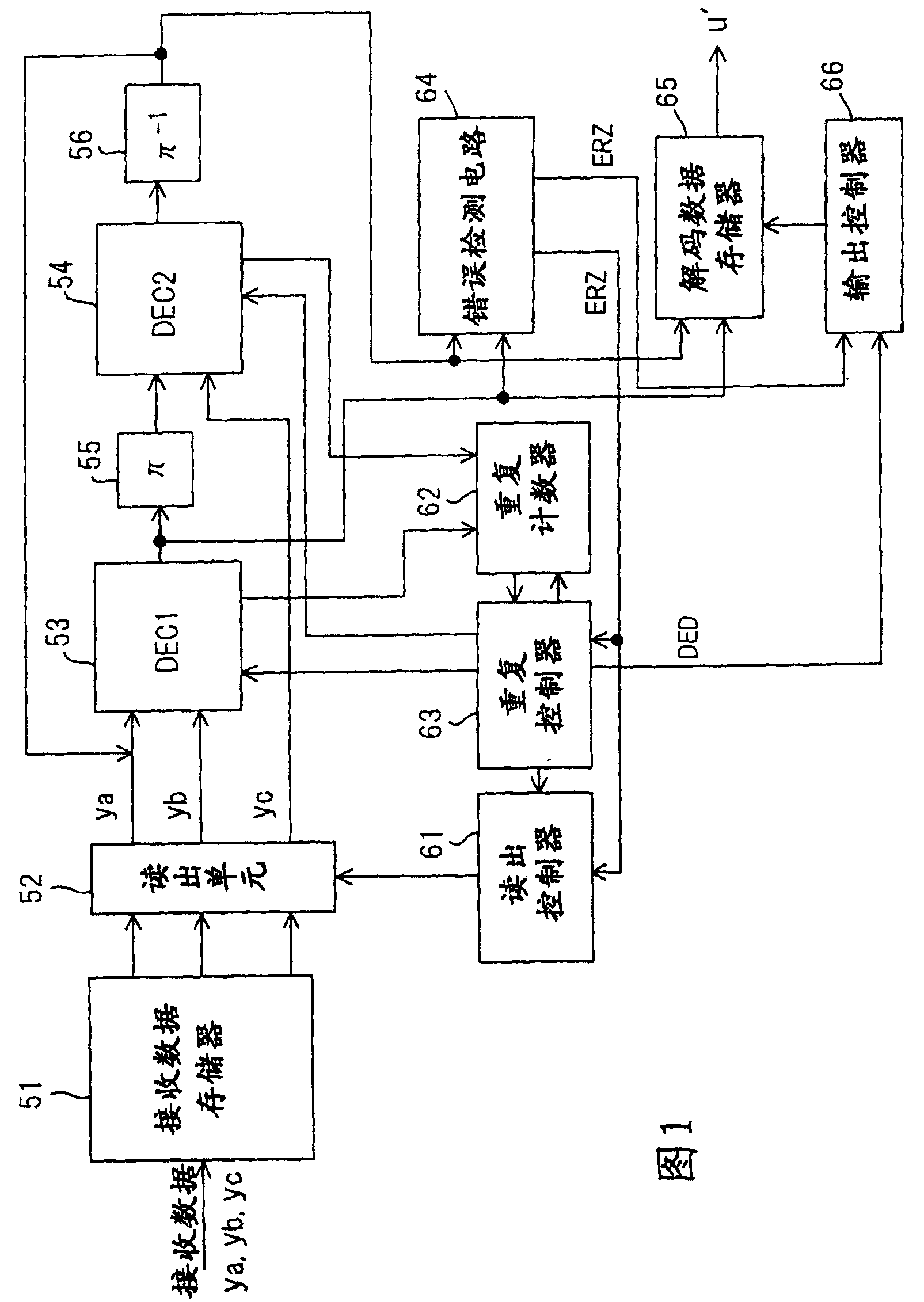
[0061] figure 1 is a block diagram of the accelerated decoder according to the first embodiment of the present invention, wherein ya, yb, and yc represent the received signals affected by noise and attenuation due to passing through the communication path of the coded data xa, xb, and xc output by the transmitting end. The coded data xa is the information data u itself, the coded data xb is the data obtained by convolutionally coding the information data u, and the coded data xc is the data obtained by interleaving the information data u and then convolutionally coding the interleaved result.
[0062] Received data memory 51 stores all received signals ya, yb, yc in units of accelerated code units, and readout unit 52 reads received data ya, yb, yc from the memory at an appropriate moment and inputs the data into First and second primary decoders (DEC1, DEC2) 53,54. The first and second primary decoders 53, 54 perform the decoding process according to the well-known MAP (Max...
no. 2 example
[0076] image 3 An embodiment of an accelerated decoder is shown, where a single primary decoder is employed.
[0077] Here a primary decoder 21 is implemented in a time-sharing manner: (1) by figure 1 The first primary decoder 53 uses the received signal Ya, yb and decodes the second half of the result to perform the decoding process (the first half of the decoding process), and (2) by figure 1 The second primary decoder 54 performs a decoding process using the received signal yc and the result of decoding the first half (second half of the decoding process). In other words, the timing of the decoding operation is divided into a first timing at which the first (first half) decoding process is performed and a second timing at which the second (second half) decoding process is performed, the first half of the decoding process at the first timing is executed, and the second half of the decoding process is executed at the second timing.
[0078] At the first timing moment wh...
no. 3 example
[0084] In prior art, such as Figure 18 As shown in (b), the error is dispersed among multiple information blocks, and the error rate on a per-block basis increases, and if the retransmission control is performed in units of information blocks, the number of retransmissions will increase . Therefore, in the case of retransmission, it is more advantageous to concentrate errors than to disperse them. With convolutional coding, the error distribution pattern in the decoding result of the primary decoder is bursty in nature. Utilizing this property makes it possible to directly output the decoding result without interleaving or deinterleaving.
[0085] Figure 4 The block diagram of shows the third embodiment of the present invention, in which the error generation pattern contained in the decoding result (decoded data) appears to be bursty.
[0086] The interleaver 30 interleaves the received signal ya and inputs the result to the first primary decoder 31 . The first primary ...
PUM
 Abstract
Description
Claims
Application Information
 - R&D
- Intellectual Property
- Life Sciences
- Materials
- Tech Scout
- Unparalleled Data Quality
- Higher Quality Content
- 60% Fewer Hallucinations
Browse by: Latest US Patents, China's latest patents, Technical Efficacy Thesaurus, Application Domain, Technology Topic, Popular Technical Reports.
© 2025 PatSnap. All rights reserved.Legal|Privacy policy|Modern Slavery Act Transparency Statement|Sitemap|About US| Contact US: help@patsnap.com