Check patentability & draft patents in minutes with Patsnap Eureka AI!

Slidable boring tool with fine adjustment

A boring and boring machine technology, applied in the direction of boring/drilling, boring head, tool holder accessories, etc., can solve the problems of detrimental CNC boring machine speed and economic benefits, inflexible labor intensity, etc.

Inactive Publication Date: 2005-09-07
CARDEMON D B A CAR TEC COM
View PDF3 Cites 11 Cited by
  • Summary
  • Abstract
  • Description
  • Claims
  • Application Information

AI Technical Summary

Problems solved by technology

This slow, inflexible and labor intensive method of adjustment detracts from the speed and economics of the CNC boring machine due to the need for the operator to stop the CNC boring machine during the adjustment period

Method used


Image

  • Slidable boring tool with fine adjustment
  • Slidable boring tool with fine adjustment
  • Slidable boring tool with fine adjustment

Examples


Embodiment Construction

[0173] In order to facilitate understanding of the principles of the present invention, the following describes the embodiments shown in the drawings and specific language is used to explain these embodiments. It should be understood, however, that these examples do not limit the scope of the invention, and such changes and other modifications in the exemplary apparatus, as well as other applications of the principles of the invention, are also contemplated as would normally occur to those skilled in the invention. .

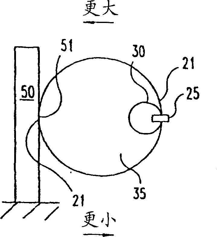
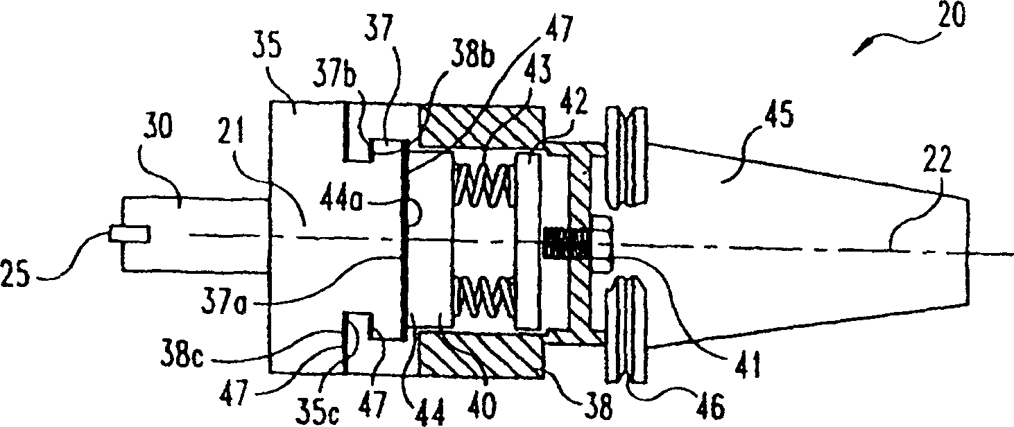
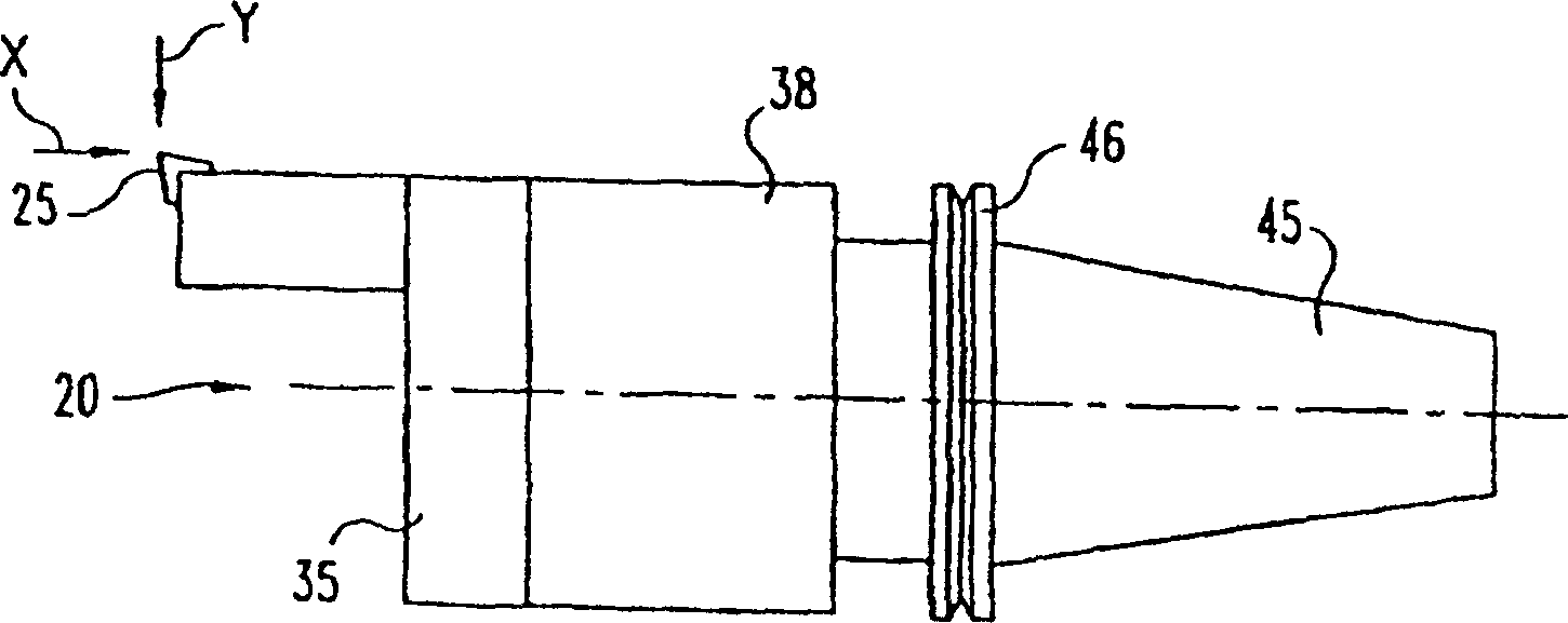
[0174] The present invention relates both to an apparatus and a method for an operator to adjust the lateral position of a cutting tool during a machining operation, such as adjusting a cutting tool for boring a hole with a CNC boring machine. According to one embodiment of the invention, the cutting tool or the cutting tool holder is connected to a connection part of the machine and is movable relative to the connection part. In yet another embodiment, the cut...


PUM


Abstract

Methods and apparatus for fine adjustment of the position of a cutting tool clamp (35) includes a CNC hol boring machine, the cutting tool clamp (35) which is slidably coupled to the coupling member (45) and a slidable adjustment member (21). A frictional force resists movement of the cutting tool clamp (35). The frictional force is sufficient to retain the position of the cutting tool clamp (35) during machining operations. However, the frictional force is insufficient to resist an adjusting force applied by the adjustment member (21). Sliding motion of the adjustment member (21), either by pulling or pushing the member, results in movement of the cutting tool clamp (35). In one embodiment, the cutting tool clamp (35) and the adjustment member (21) are slidable in different directions.

Description

technical field [0001] The invention relates to a cutter device in machining, in particular to a boring device used in a computer numerical control (CNC) boring machine. Background technique [0002] Many products such as automotive transmissions and cylinder blocks include precision bores. These bores are made by a cutting tool supported by a boring device which in turn is driven by a boring machine. In many cases, the boring machine is a computer numerically controlled (CNC) boring machine because of flexibility, economy, and accuracy. Many CNC boring machines are capable of performing a variety of operations on the workpiece, including boring many different sized holes by automatically selecting previously adjusted boring devices on the tool face. [0003] However, many boring devices require manual adjustment by the machine operator. Some currently used boring devices, such as the 3F-JBD Boring and Facing Head produced by the CriterionMachine Words factory in Costa Me...

Claims


Application Information

Patent Timeline
Patent Type & Authority Applications(China)
IPC IPC(8): B23B39/00B23B3/00B23B29/034B23B39/08
CPCB23B2260/03B23B2228/10B23B29/03417B23B2270/08B23B2250/16B23B2260/136B23B29/03403B23B29/03492Y10T82/10
Inventor R·A·卡德蒙J·贝克
Owner CARDEMON D B A CAR TEC COM
Features
  • R&D
  • Intellectual Property
  • Life Sciences
  • Materials
  • Tech Scout
  • Unparalleled Data Quality
  • Higher Quality Content
  • 60% Fewer Hallucinations
Learn More