Check patentability & draft patents in minutes with Patsnap Eureka AI!

Integrated circuit with automatic polarity detection and configuration

A driving circuit and polarity technology, applied in logic circuits, transducer circuits, current indication directions, etc., can solve problems such as delays, unwanted clicks and crackles

Inactive Publication Date: 2011-10-26
CIRRUS LOGIC INC
View PDF1 Cites 0 Cited by
  • Summary
  • Abstract
  • Description
  • Claims
  • Application Information

AI Technical Summary

Problems solved by technology

However, configurable polarity requires additional dedicated pins, or a register that can be set via the control port whenever the chip is powered on or reset
A disadvantage of using registers is that there may still be a delay after the chip comes out of reset until the registers are configured
During this time, the squelch node can be unsquelched, resulting in unwanted clicks and crackles to be eliminated

Method used


Image

  • Integrated circuit with automatic polarity detection and configuration
  • Integrated circuit with automatic polarity detection and configuration
  • Integrated circuit with automatic polarity detection and configuration

Examples


Embodiment Construction

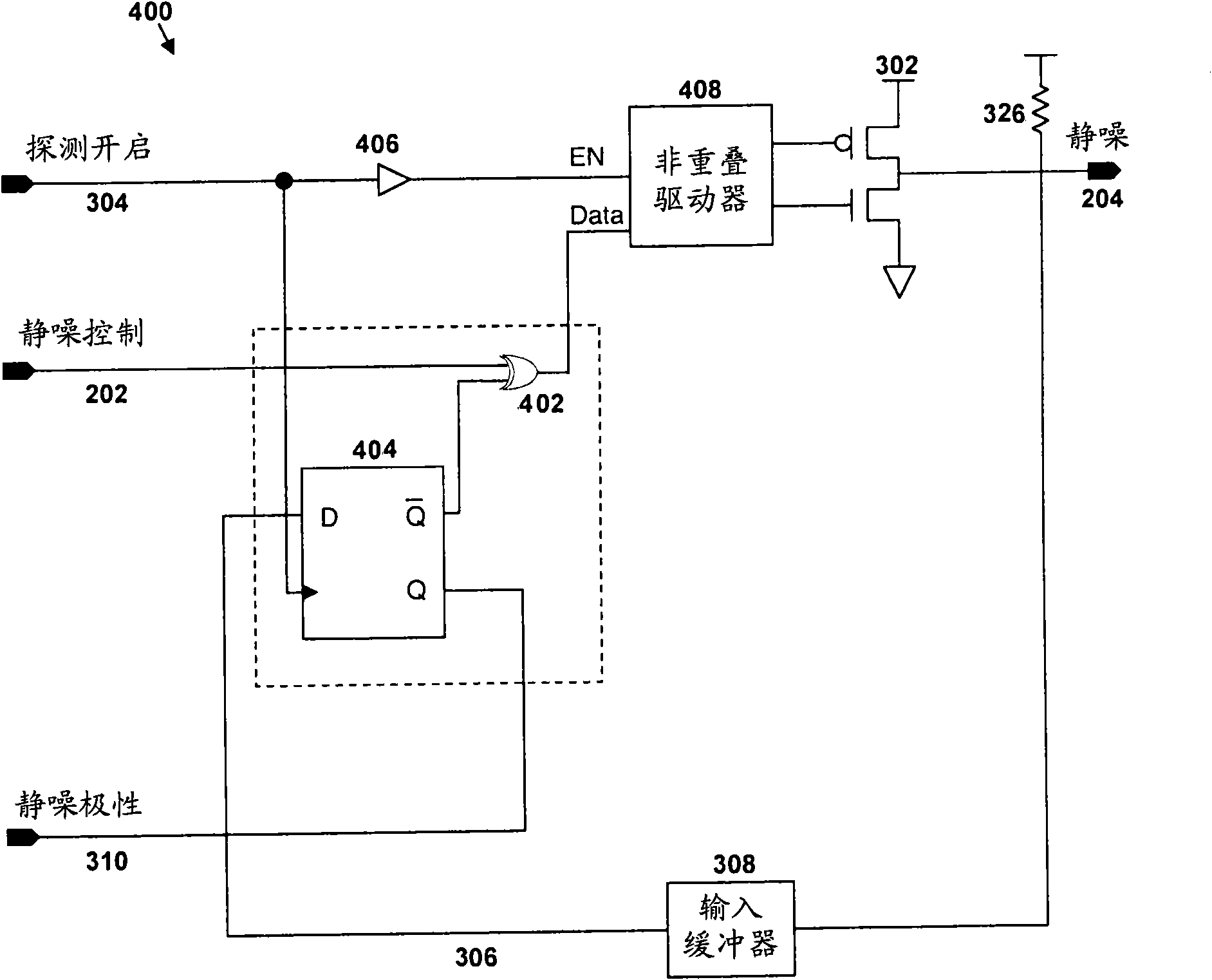
[0017] image 3 is a high level logic diagram of a polarity detector 300 included in an exemplary integrated circuit that also includes a DAC, in accordance with the present invention. Chips can be mounted with for example preferably belonging to Figure 1C or a squelch circuit of the type shown in 1D (if using Figure 1A or circuit in 1B and the input line drifts to the left, either circuit will self-bias to the unwanted unsquelch state) on the system board. In the following, the present invention will be described in conjunction with squelch circuits and squelch nodes; however, this description should not be considered limiting, and it should be understood that the present invention can be used in conjunction with other types of circuits , these circuits satisfy the following conditions: the polarity of the node is not known in advance, but the polarity of the node is determined at power-up or other reset. Driver circuit 302 is also included on-chip, and with figure 2 T...


PUM


Abstract

An integrated circuit on a system board is used, for example, in a digital audio device (such as a DVD or A / V receiver). The integrated circuit includes a digital-to-analog converter and the system board may include circuitry to mute the analog output of the device under certain predefined conditions. Because it may not be known in advance by the designer of the integrated circuit whether the circuit is activated by a signal in a high state (polarity) or a low state, the integrated circuit includes a detector which detects and stores the required polarity. When it is necessary for the circuitto be activated, the detector provides a signal of the correct polarity.

Description

technical field [0001] The present invention generally relates to the field of integrated circuits, and more particularly to detecting and configuring the polarity of circuit leads (pins, also known as pins). Background technique [0002] Integrated circuits, or "chips," are typically mounted or assembled on a system circuit board that will eventually be mounted on an end product. Typically, integrated circuits are purchased for use in several (or many) different end products, often made by different manufacturers. It should be realized that it is impractical to have different chip designs for similar applications. However, in the past, it has also been impractical to automatically change a chip to work with many different system boards. [0003] For example, audio equipment such as DVD equipment and audio / video (A / V) receivers include digital audio integrated circuits having, among other functional components, digital-to-analog converters (DACs) ), for outputting an anal...

Claims


Application Information

Patent Timeline
Patent Type & Authority Patents(China)
IPC IPC(8): H03K17/16H03F3/38H04R3/00H03F1/00H03F3/217H03K17/22
CPCH03F3/2171G01R19/14H03K19/00
Inventor 易鹤龄戴维·奥利文包姆
Owner CIRRUS LOGIC INC
Features
  • R&D
  • Intellectual Property
  • Life Sciences
  • Materials
  • Tech Scout
  • Unparalleled Data Quality
  • Higher Quality Content
  • 60% Fewer Hallucinations
Learn More