Flexible cavity liquid spraying device driven by marmen
A technology of memory alloy and liquid injection device, which is applied in the direction of injection device, liquid injection device, etc., can solve problems such as leakage and complex structure, and achieve the effect of low driving voltage, simple control system and simple structure
- Summary
- Abstract
- Description
- Claims
- Application Information
AI Technical Summary
Problems solved by technology
Method used
Image
Examples
specific Embodiment approach 1
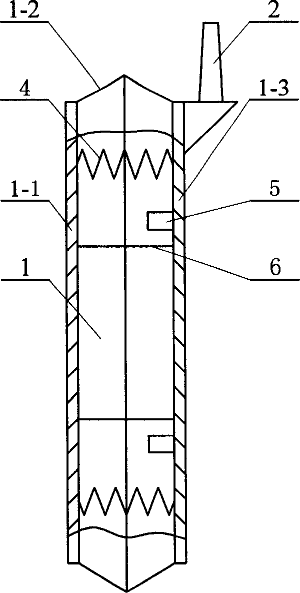
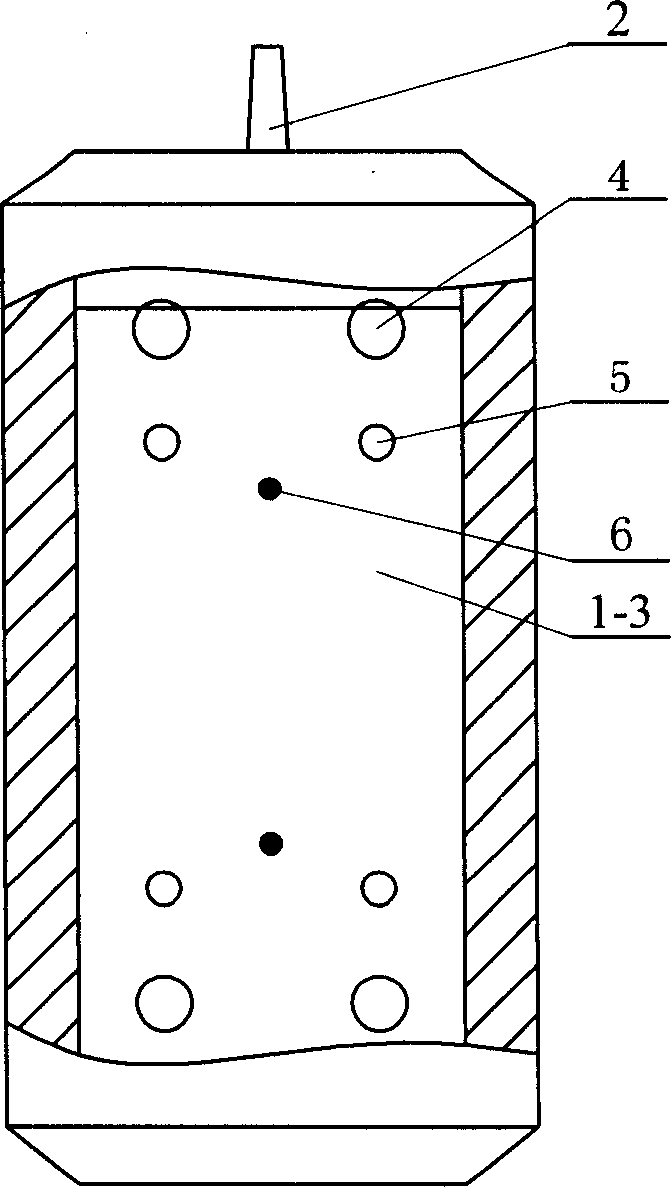
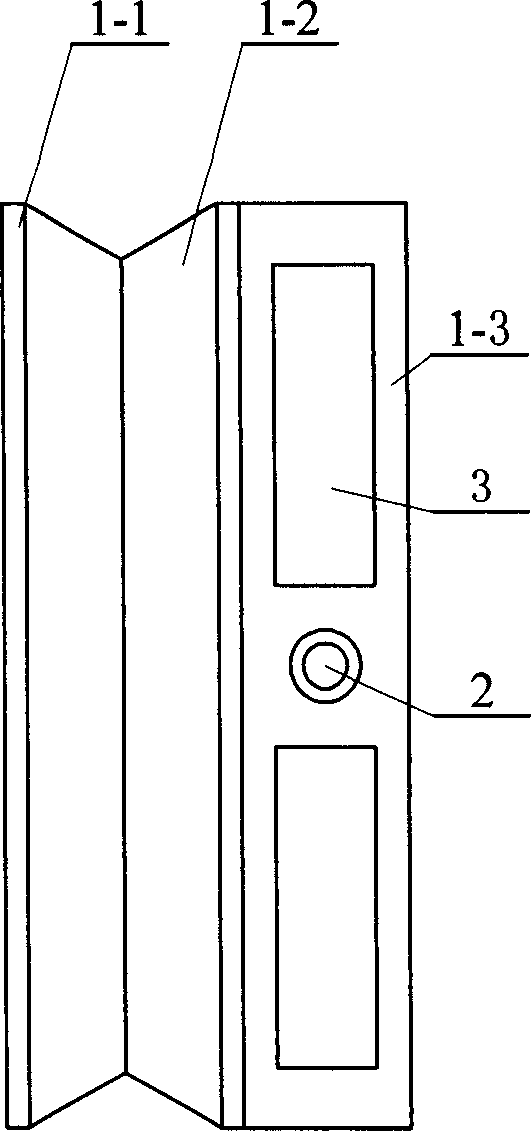
[0021] Specific implementation mode one: see Figure 1~3 , the liquid injection device of this embodiment is composed of a cavity 1, a nozzle 2, a liquid inlet valve 3, a shape memory alloy driver 4, a limit post 5 and a limit pull wire 6, the cavity 1 is connected to the nozzle 2, and the type The cavity 1 is jointly surrounded by a dynamic pressure plate 1-1, a flexible side skin 1-2 and a static pressure plate 1-3, and the left end surface and the right end surface of the flexible side skin 1-2 are respectively connected with a dynamic pressure plate 1-1 and a static pressure plate. The pressure plate 1-3, the shape memory alloy driver 4 and the limit pull wire 6 are connected between the dynamic pressure plate 1-1 and the static pressure plate 1-3, and the limit column 5 is installed on the inner end surface of the static pressure plate 1-3, and the The liquid valve 3 is installed on the static pressure plate 1-3 and communicates with the cavity 1. The liquid inlet valve ...
specific Embodiment approach 2
[0024] Specific implementation mode two: see Figure 4~6 The difference between this embodiment and the first embodiment is that it also includes a return spring 7, the return spring 7 is located between the dynamic pressure plate 1-1 and the static pressure plate 1-3, and the shape memory alloy driver 4 is a one-way shape memory Alloy drive. Since the one-way shape memory alloy only has the function of memorizing the shape of the high-temperature parent phase, when the temperature is lowered to make it in the low-temperature martensitic phase state, it cannot change its shape spontaneously, and only with the help of external force can the two-way action be realized. This embodiment is realized by means of return springs 7, wherein the number of return springs is three or more.
[0025] working principle:
[0026] The whole liquid spraying device is submerged in the liquid, and the nozzle 2 can also protrude out of the liquid surface. When working, the shape memory alloy dri...
specific Embodiment approach 3
[0027] Specific implementation mode three: as Figure 7-10As shown, this embodiment is a flexible cavity liquid injection device that feeds liquid from the back of the static pressure plate 1-3, and the one-way liquid inlet valve 3 is located at the back of the static pressure plate 1-3. When the cavity 1 expands, the one-way liquid inlet valve 3 is opened to realize liquid inlet from the back. Due to the larger area of the back of the static pressure plate 1-3, a larger liquid inlet can be opened to realize rapid liquid inlet and increase the frequency of liquid spraying.
PUM
 Abstract
Description
Claims
Application Information
 - R&D Engineer
- R&D Manager
- IP Professional
- Industry Leading Data Capabilities
- Powerful AI technology
- Patent DNA Extraction
Browse by: Latest US Patents, China's latest patents, Technical Efficacy Thesaurus, Application Domain, Technology Topic, Popular Technical Reports.
© 2024 PatSnap. All rights reserved.Legal|Privacy policy|Modern Slavery Act Transparency Statement|Sitemap|About US| Contact US: help@patsnap.com


