Built-in cooking heater
A cooker and embedded technology, applied in the field of embedded heating cookers, can solve problems such as main body failure
- Summary
- Abstract
- Description
- Claims
- Application Information
AI Technical Summary
Problems solved by technology
Method used
Image


Examples
Embodiment approach 1
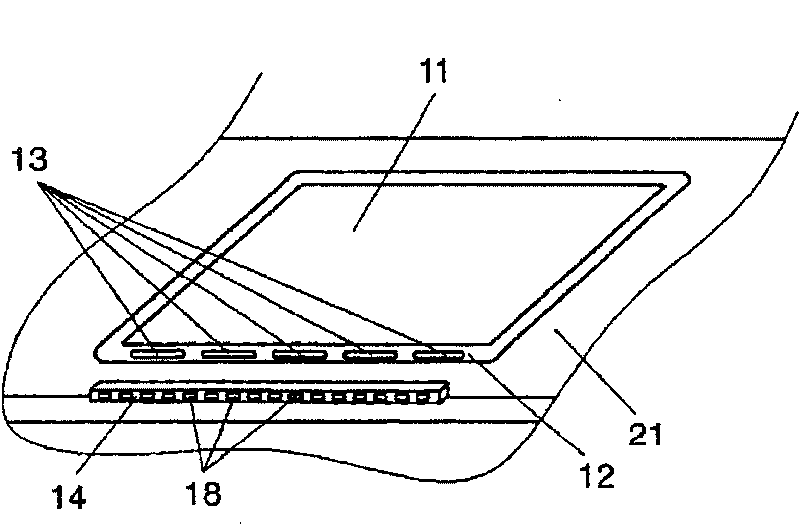
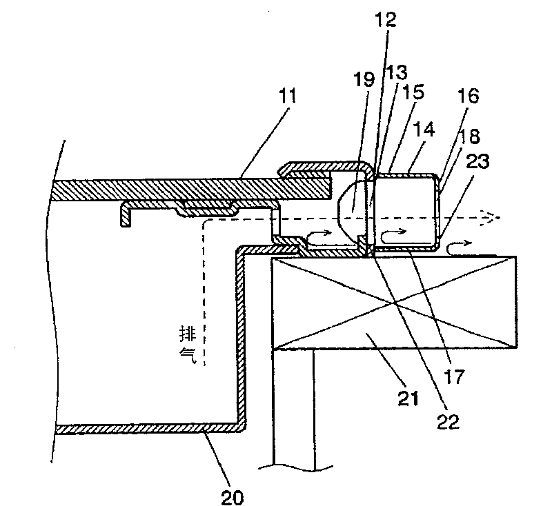
[0029] use Figure 1A-4 Embodiment 1 will be described. Figure 1~ Figure 4 Among them, on the top 11 constituting the main body and on the first side wall 12 at the rear, a plurality of openings 13 for air intake / exhaust are provided for cooling the inside of the main body. Also, the top 11 is equivalent to the frame body 1 and the top plate 2 described in the prior art.
[0030] Furthermore, a cover 14 is attached to the outside of the first side wall 12 so as to cover the first opening 13 . The cover 14 has a top surface 15 , a second side wall 16 , and a bottom surface 17 , and the second side wall 16 has a plurality of second openings 18 . Elastic bodies 19 having elasticity are formed on both sides of the cover 14 . The elastic body 19 fits on both sides of the first opening 13 and is therefore detachably attached to the top 11 . The casing 20 constituting the main body is located inside the top 11 , and the main body is arranged in the cabinet 21 .
[0031] Accord...
Embodiment approach 2
[0039] use Figure 5 and Image 6 Embodiment 2 will be described. Figure 5Since the basic configuration is the same as that of Embodiment 1, only the difference in configuration will be described. The cover 14 has a substantially U-shape and is composed of a top surface 15 , a second side wall 16 , and a bottom surface 17 . On both sides of the cover 14, a resin protective frame 24 is fixed in holes provided on the top surface 15 and the bottom surface 17 by claw fitting. The protective frame 24 is provided with a convex portion 25 having a rounded tip and forming a guide shape at a central portion. The cover 14 and the protective frame 24 are formed as an integral part by fitting claws. Regarding the structure of the suction / exhaust portion of the built-in heating cooker constructed as above, its operation and function will be described below. Regarding the operation and function, only the parts different from those in the first embodiment will be described. Others are...
Embodiment approach 3
[0043] use Figure 7 Embodiment 3 will be described. The basic configuration is the same as that of Embodiment 1, so only the difference in configuration will be described. The cover 14 is composed of two short covers, which are respectively detachably mounted on the first side wall 12 behind the top 11.
[0044] The suction / exhaust portion of the cooker constructed as above is constituted, and its operation and function will be described below. Regarding the operation and function, only the parts different from those in the first embodiment will be described. Consider the case where the cover 14 is removed from the top 11 . Each short cover can be made with less than half of one side of the main body, that is, about 25 cm in length. Therefore, when it is dirty and needs to be cleaned, it is easy to clean due to its small size, and it is not necessary to select a place for drying after cleaning. In addition, since it is a size that can be put into a dish washer and dryer ...
PUM
 Abstract
Description
Claims
Application Information
 - R&D
- Intellectual Property
- Life Sciences
- Materials
- Tech Scout
- Unparalleled Data Quality
- Higher Quality Content
- 60% Fewer Hallucinations
Browse by: Latest US Patents, China's latest patents, Technical Efficacy Thesaurus, Application Domain, Technology Topic, Popular Technical Reports.
© 2025 PatSnap. All rights reserved.Legal|Privacy policy|Modern Slavery Act Transparency Statement|Sitemap|About US| Contact US: help@patsnap.com