Water transportation planning device, method, program, recording medium, and server therefor

A technology of water utilization and planning, applied in water supply equipment, water supply equipment, water/sewage treatment, etc., can solve problems such as inability to calculate costs, inability to apply, and failure to consider raw water purchase fees, etc., to save resources, save energy, cost-saving effect

Inactive Publication Date: 2006-05-31
HITACHI LTD
View PDF7 Cites 14 Cited by
  • Summary
  • Abstract
  • Description
  • Claims
  • Application Information

AI Technical Summary

Problems solved by technology

[0012] The technique described in JP-A-11-203268 (Patent Document 2) targets multiple wells or water distribution tanks, and simulates only the amount of water intake and distribution flow, and calculates the amount of electricity or chemicals related to water treatment, etc. The cost of the
In addition, since only clean well water is used as the object, it cannot be applied to the water intake plan of the water purification plant with water sources with fluctuating water quality.
[0013] In the technology described in Japanese Patent Laid-Open No. 8-128078 (Patent Document 3), consumption resources per unit flow rate (yen/m 3 ) to calculate the cost of clean water generation, and cannot calculate the change in the amount of chemicals or electricity for water treatment when the water quality changes
Therefore, there is a problem that it is not possible to reflect changes in the quality of raw water in the production cost of purified water.
In addition, when planning the intake of water from a plurality of water sources with different water quality, there is a problem that the intake of each water source cannot be obtained appropriately
Furthermore, there is a problem that the cost cannot be calculated when there are multiple water treatment systems with different styles in the water purification plant.
Moreover, the

Method used


Image

  • Water transportation planning device, method, program, recording medium, and server therefor
  • Water transportation planning device, method, program, recording medium, and server therefor
  • Water transportation planning device, method, program, recording medium, and server therefor

Examples


Example Embodiment

[0045] Hereinafter, an embodiment of the present invention will be described with reference to the drawings. This embodiment is an example of applying the present invention to the preparation of the planned value of the water intake.

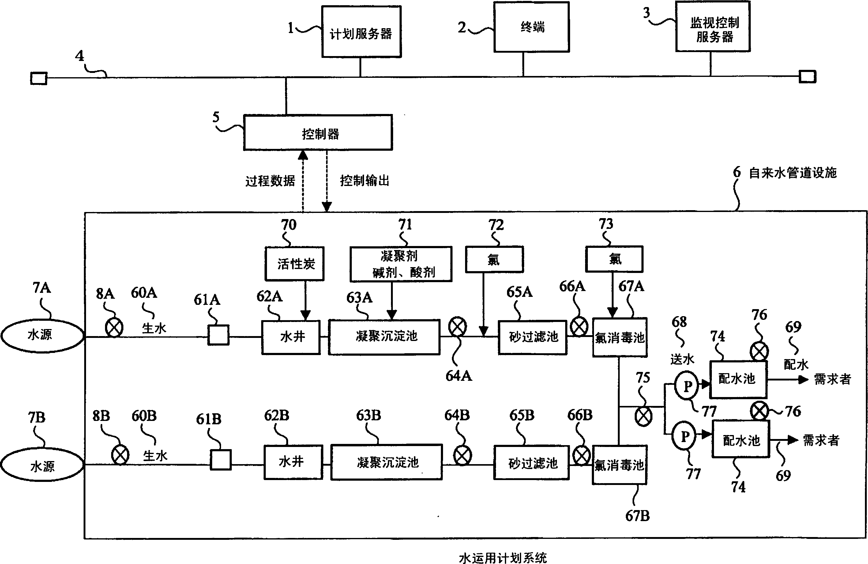
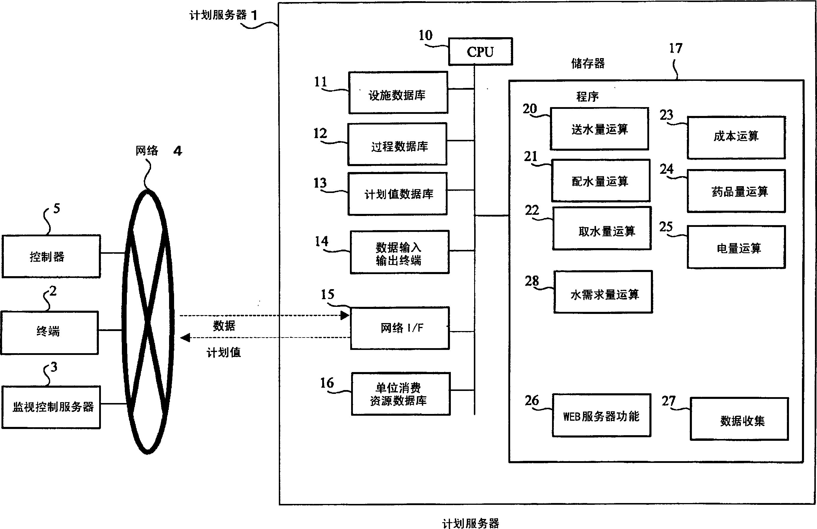
[0046] figure 1 It is a diagram showing an example of the overall schematic configuration of the water operation system to which the present invention is applied. The water operation system is composed of a planning server 1, a terminal 2, a monitoring control server 3, a network 4, a controller 5, and a water pipe facility 6.

[0047] The water pipe facility 6 is a mechanism for taking water from two water sources (surface water such as rivers, reservoirs, etc.) 7A and 7B with different water quality, and has two water treatment series (series A and series) that correspond to the water sources 7A and 7B one-to-one. B) constitute a water purification plant and 2 distribution pools.

[0048] Taking the water treatment series A as an example, the st...


PUM


Abstract

PROBLEM TO BE SOLVED: To make a water operation plan for minimizing cost for water transportation and water treatment in water supply facility for taking water from a plurality of water sources having different water quality.

SOLUTION: The water operation plan for the water supply facility is made by a water operation planning device 1 provided with a water transportation cost computing means for computing water transportation cost in the water supply facility 6 when taking water from each water source 7A, 7B including cost for purchasing raw water and a water transportation amount planned value computing means for computing a planned value of water transportation amount in the water supply facility 6 based on the water transportation cost computed by the water transportation cost computing means.

COPYRIGHT: (C)2006,JPO&NCIPI

Description

technical field [0001] The present invention relates to a device or method for drawing up a water utilization plan for a water supply pipeline facility that draws water from a plurality of water sources. Background technique [0002] Water piping facilities play an important role in the stable supply of safe water. Raw water taken from surface water (rivers, reservoirs, lakes, etc.), groundwater, underground river water, etc., is treated in the water purification plant to remove pollutants and harmful substances, and is sent to the grassroots through the water distribution tank or water distribution pipe network Supply to those in need. In water pipeline facilities, generally speaking, water is drawn from multiple water sources, there are multiple water distribution pipe networks or multiple water treatment systems, and there are also multiple water distribution tanks, and the water distribution pipe networks are distributed in a wide area. And through the computer system ...

Claims


Application Information

Patent Timeline
IPC IPC(8): C02F1/00E03B1/00G06Q50/00G06Q50/06
CPCY02A20/152
Inventor 原直树木村文智
Owner HITACHI LTD
Why Eureka
Try Eureka