Supercharge Your Innovation With Domain-Expert AI Agents!

Plasma display apparatus

A plasma display and plasma display panel technology, which is applied to static indicators, instruments, identification devices, etc., can solve problems such as wrong discharges, and achieve the effect of reducing wrong discharges

Inactive Publication Date: 2006-06-14
LG ELECTRONICS INC
View PDF0 Cites 0 Cited by
  • Summary
  • Abstract
  • Description
  • Claims
  • Application Information

AI Technical Summary

Problems solved by technology

[0018] In general, a conventional plasma display panel driven by a driving waveform has a problem that erroneous discharge is generated during an address period or a support period when the ambient temperature is too high or too low

Method used


Image

  • Plasma display apparatus
  • Plasma display apparatus
  • Plasma display apparatus

Examples


Embodiment Construction

[0034] Preferred embodiments of the present invention are explained in more detail with reference to the accompanying drawings.

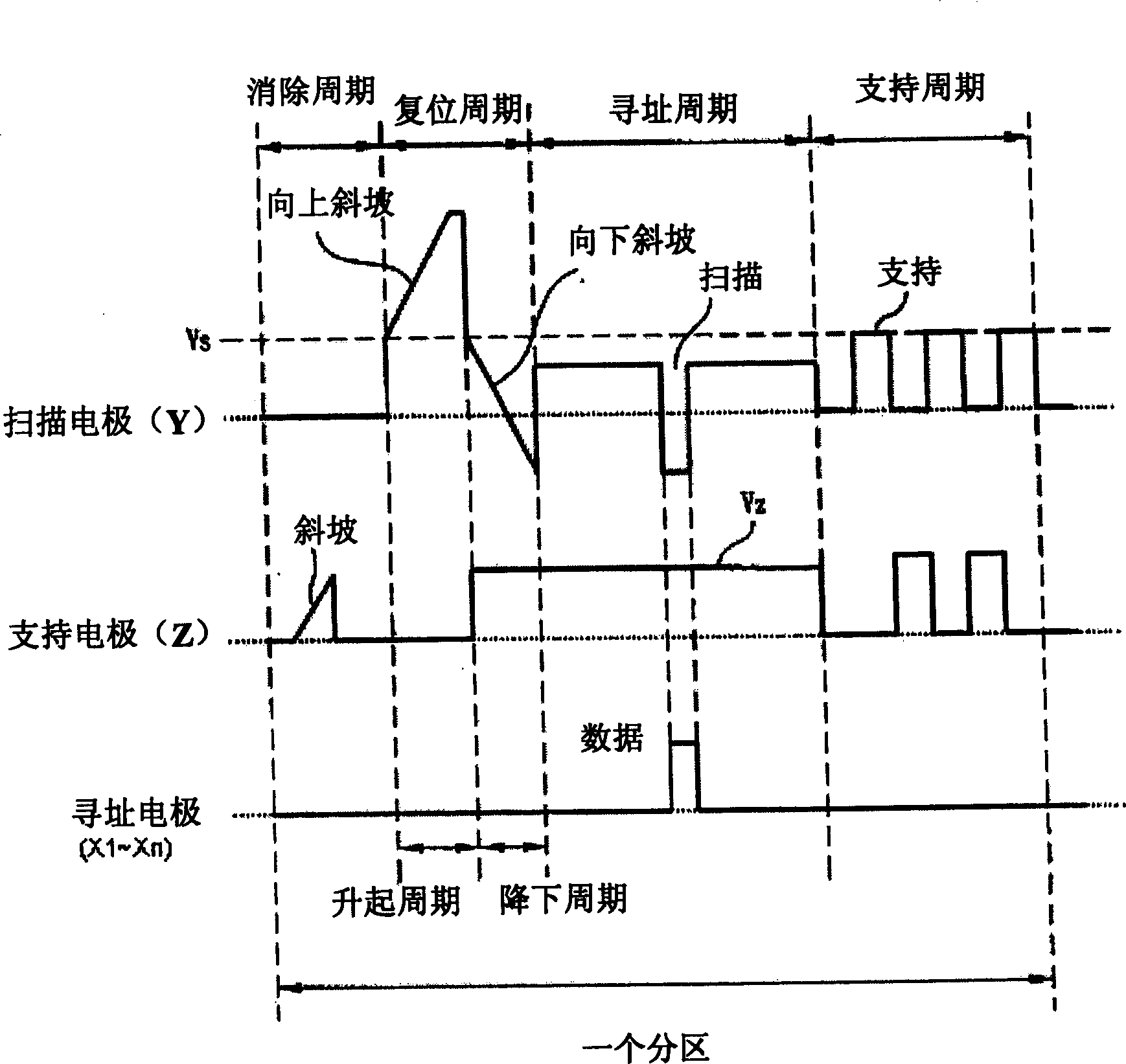
[0035] A plasma display according to the present invention includes: a plasma display panel including a scan electrode and a support electrode; a scan driver for applying a negative voltage to the scan electrode before a reset period when the scan electrode is applied with a positive voltage; and a support driver for A positive voltage is applied to the support electrode when the scan electrode is applied with a negative voltage.

[0036] The minimum value of the negative voltage applied to the scan electrodes is equal to the minimum value of the scan pulse voltage applied in the address period.

[0037] The absolute value of the negative voltage is greater than the absolute value of the positive voltage applied to the supporting electrode.

[0038] The magnitude of the positive voltage applied to the support electrode is greater than 150V and less...


PUM


Abstract

The present invention relates to plasma displays. A plasma display according to the present invention includes: a plasma display panel including a scan electrode and a support electrode; a scan driver for applying a negative voltage to the scan electrode before a reset period when the scan electrode is applied with a positive voltage; and a support driver for A positive voltage is applied to the support electrode when the scan electrode is applied with a negative voltage.

Description

technical field [0001] The present invention relates to plasma displays. Background technique [0002] Generally, in a plasma display panel, a barrier rib formed between a front substrate and a rear substrate forms a unit cell. Each cell is filled with a main discharge gas such as neon (Ne), helium (He), or a mixed gas of Ne and He (Ne+He), and an inert gas including a small amount of xenon. If an inert gas is discharged with a high-frequency voltage, vacuum ultraviolet rays are generated. Phosphors formed between the partition walls emit light to display images. Such a plasma display panel can be made light and thin, and thus has come into the center of attention as a next-generation display device. [0003] figure 1 The construction of a general plasma display panel is shown. [0004] like figure 1 As shown, the plasma display panel includes a front substrate 100 and a rear substrate 110 . The front substrate 100 has a plurality of support electrode pairs arranged o...

Claims


Application Information

Patent Timeline
Patent Type & Authority Applications(China)
IPC IPC(8): G09F9/313G09G3/20G09G3/288G09G3/291G09G3/298
CPCG09G3/2927G09G3/294G09G2310/066G09G2320/041G09G3/292G09G3/296
Inventor 李基凡郑允权
Owner LG ELECTRONICS INC
Features
  • R&D
  • Intellectual Property
  • Life Sciences
  • Materials
  • Tech Scout
  • Unparalleled Data Quality
  • Higher Quality Content
  • 60% Fewer Hallucinations
Learn More