Valve assembly and ink cartridge
A valve assembly and valve cavity technology, used in safety valves, balance valves, valve devices, etc., can solve problems such as threshold uncertainty, fatigue, and inconsistent performance indicators of batch products, and achieve stable work and consistent performance.
- Summary
- Abstract
- Description
- Claims
- Application Information
AI Technical Summary
Problems solved by technology
Method used
Image

Examples
Example
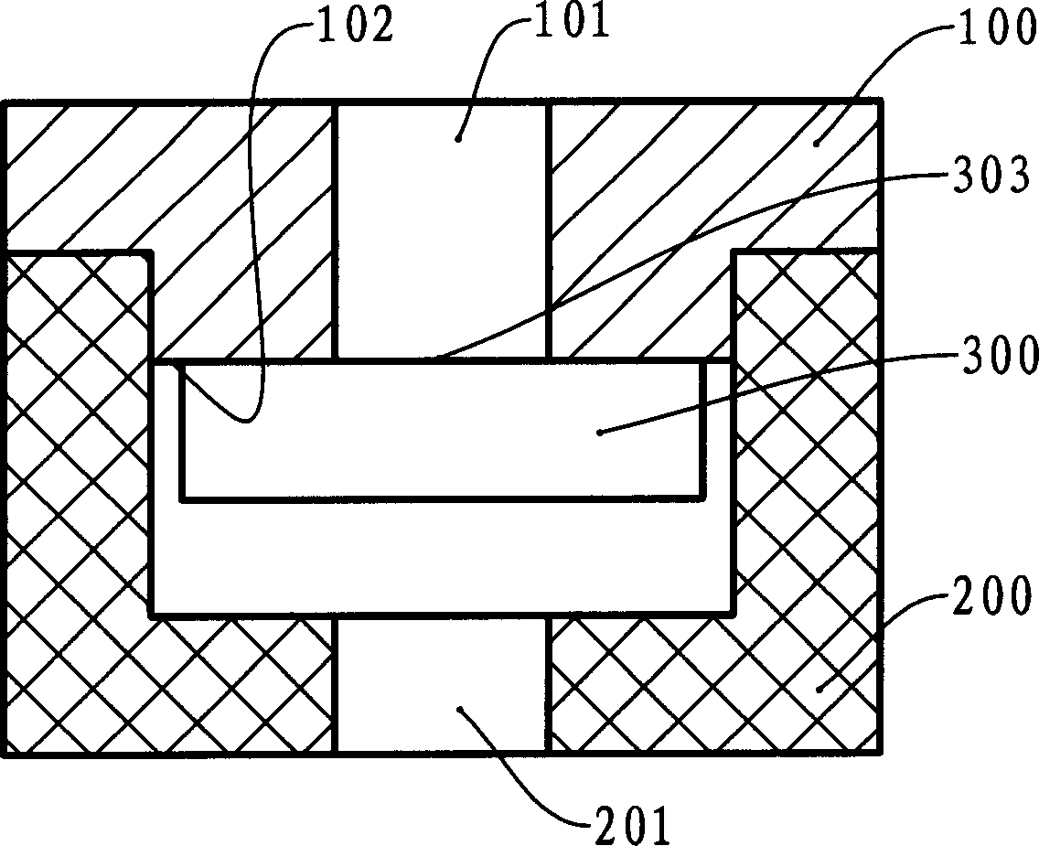
[0025] First embodiment:
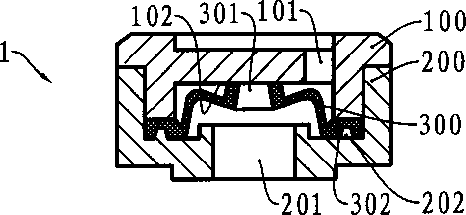
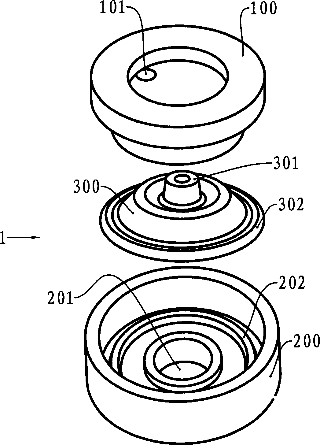
[0026] see image 3 , this example is a valve assembly, the valve body 300 is located in the valve chamber formed by the combination of the valve holder 200 and the valve cover 100, the valve chamber has an inlet 101 and an outlet 201, wherein the valve cover 100 and the valve body 100 are both made of a magnetic system The inlet surface 102 is opposite to the valve surface 303 with opposite magnetic poles. Under the action of magnetic attraction, the valve surface 303 is attracted to the inlet surface to block the fluid channel between the inlet 101 and the outlet 201 . When the valve assembly is connected in series in a fluid channel, the pressure at the inlet 101 is high and the pressure at the outlet 201 is low, and the pressure difference is greater than the magnetic attraction force, the valve body 300 will go down under the pressure difference, opening the inlet 101 and the outlet 201. Fluid passage between outlets 201.
Example
[0027] Second embodiment:
[0028] see Figure 4 , this example is also a valve assembly, the valve body 300 is located in the valve chamber formed by the combination of the valve holder 200 and the valve cover 100, the valve chamber has an inlet 101 and an outlet 201, the valve body 100 is made of a magnetic body, and another magnetic body 402 Fixed on the bottom surface of the valve holder 200, the magnetic body 400 has a through hole 401 docked with the outlet 201, the upper surface of the magnetic body 400 is opposite to the lower surface 304 of the valve body 300 with the same magnetic polarity, and the repulsive force between the two makes the valve surface 303 is closely attached to the inlet surface 102 to block the fluid channel between the inlet 101 and the outlet 201 . When the valve assembly is connected in series in a fluid channel, the pressure at the inlet 101 is high and the pressure at the outlet 201 is low, and the pressure difference is greater than the abo...
Example
[0029] Third embodiment:
[0030] see Figure 5 , this example is a valve assembly that is basically the same as the first embodiment, the difference is that the valve body 300 is made of a magnetic body, and the valve cover 100 is made of a magnetic conductor, or, the valve cover 100 is made of a magnetic body and the valve body 300 is made of a magnetic conductor, and also relies on the magnetic force between the two to keep the valve surface 303 close to the inlet surface 102 and block the fluid passage between the inlet 101 and the outlet 201 . When the valve assembly is connected in series in a fluid channel, the pressure at the inlet 101 is high and the pressure at the outlet 201 is low, and the pressure difference is greater than the above-mentioned repulsive force, the valve body 300 will go down under the action of the pressure difference to open the inlet 101 and the fluid channel between outlet 201.
PUM
 Abstract
Description
Claims
Application Information
 - R&D Engineer
- R&D Manager
- IP Professional
- Industry Leading Data Capabilities
- Powerful AI technology
- Patent DNA Extraction
Browse by: Latest US Patents, China's latest patents, Technical Efficacy Thesaurus, Application Domain, Technology Topic.
© 2024 PatSnap. All rights reserved.Legal|Privacy policy|Modern Slavery Act Transparency Statement|Sitemap