Apparatus and method for detecting antenna feedback fault point of narrow-band base-station system

A fault point and base station technology, which is applied in the direction of measuring devices, measuring electrical variables, measuring resistance/reactance/impedance, etc., which can solve the problem of decreased detection accuracy, reduced detection accuracy, and no antenna-feeder fault point location. Antenna-feeder fault point VSWR measurement plan and other issues to achieve the effect of increasing the distance

Active Publication Date: 2006-10-25
HUAWEI TECH CO LTD
View PDF0 Cites 16 Cited by
  • Summary
  • Abstract
  • Description
  • Claims
  • Application Information

AI Technical Summary

Problems solved by technology

However, for the antenna feeder of the narrowband base station system, the sweeping range of the frequency sweep source cannot exceed the passband range of the receive filter of the base station RF front end
This is because the signal whose frequency is outside the passband range of the receiving filter of the radio frequency front end of the base station will generate multiple reflections when detecting the fault point of the antenna feeder, which g

Method used


Image

  • Apparatus and method for detecting antenna feedback fault point of narrow-band base-station system
  • Apparatus and method for detecting antenna feedback fault point of narrow-band base-station system
  • Apparatus and method for detecting antenna feedback fault point of narrow-band base-station system

Examples


Embodiment Construction

[0053] The core idea of ​​the present invention is that, within the device for antenna fault point detection using PDFDR technology, the distance between the antenna fault point and the detection device is increased by adding a delay device, so that a higher Accurate point-of-fault detection.

[0054] In order to make the purpose, technical solution and advantages of the present invention clearer, the present invention will be further described in detail below in conjunction with the accompanying drawings and specific embodiments.

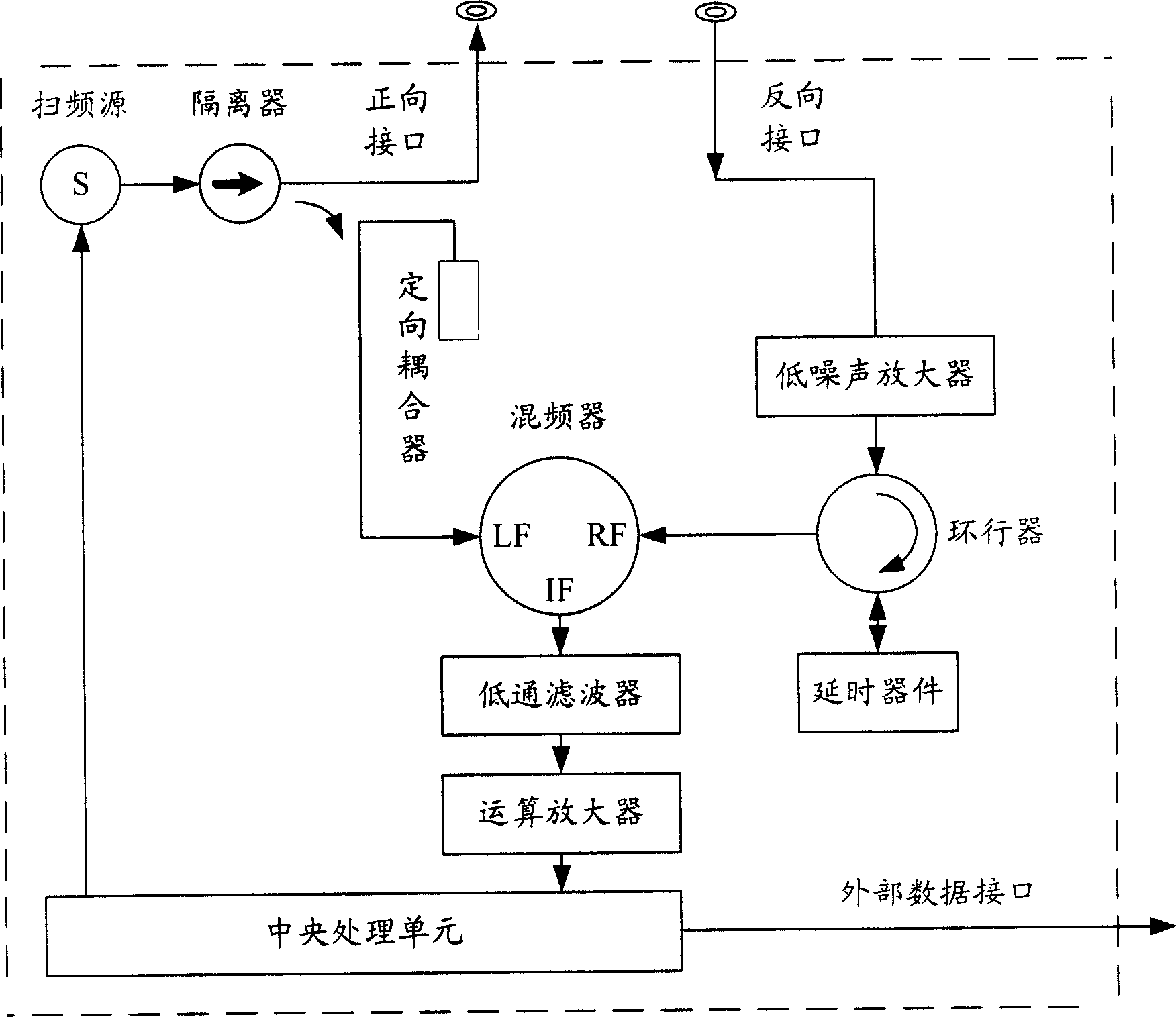
[0055] Please refer to image 3 , image 3 It is a block diagram of an antenna feeder fault point detection device for a narrowband base station system provided by the present invention.

[0056] The frequency sweep source is used to output signals of different frequencies within a certain frequency sweep range. Its input is the control signal output by the central processing unit, and the output is connected to the isolator.

[0057] The isola...


PUM


Abstract

This invention discloses a device for testing antenna fault points of narrow-band base stations including: a sweep source for generating sweep signals, part of which is output to the antenna fault points to be tested, the other part is taken as the input of a frequency mixer, a delay module used in delaying the reflection signals of the fault point and outputting them to the mixer, a mixer used in mixing the signals of the sweep and signals output by the delay time module and outputting them to a CPU, a CPU for testing the fault points of a narrow-band base station system based on the signals output by the mixer and a method for testing is also disclosed.

Description

technical field [0001] The invention relates to mobile communication technology, in particular to a device and method for locating antenna feeder fault points and measuring the voltage standing wave ratio of antenna feeder fault points in a narrowband base station system. Background technique [0002] There are two main methods for locating the fault point in the fault cable and measuring the voltage standing wave ratio (VoltageStanding Wave Ratio, VSWR) of the fault point: one is the Time Domain Reflectometer (TDR) method, and the other is the Time Domain Reflectometer (TDR) method. Is the Frequency Domain Reflectometer (FrequencyDomain Reflectometer, FDR) method. Phase Detection FDR (Phase Detection FDR, PDFDR) is one of the FDR technologies. It uses phase detection to locate fault points. It is currently mainly used in the detection of aging cables in other vehicles such as airplanes, trains, and automobiles. [0003] Please refer to figure 1 , figure 1 is the schemati...

Claims


Application Information

Patent Timeline
IPC IPC(8): G01R27/06H04B17/12
Inventor 艾鸣许海堤
Owner HUAWEI TECH CO LTD
Why Eureka
Try Eureka