Check patentability & draft patents in minutes with Patsnap Eureka AI!

Remote controlled electronic device

An electronic device and remote control technology, which is applied in non-electrical signal transmission systems, signal transmission systems, instruments, etc., can solve the problems of insensitivity of remote control reception, increase of sensors receiving non-remote control signals, malfunctions, etc.

Active Publication Date: 2006-11-29
AU OPTRONICS CORP
View PDF0 Cites 1 Cited by
  • Summary
  • Abstract
  • Description
  • Claims
  • Application Information

AI Technical Summary

Problems solved by technology

However, this type of design also increases the possibility of the sensor receiving non-remote control signals (ie noise), which seriously affects the remote control function of the electronic device
When the signal band in the surrounding environment overlaps with the band that the sensor can receive, this problem will become more serious, and even cause the sensor to be insensitive or malfunction to the remote control

Method used


Image

  • Remote controlled electronic device
  • Remote controlled electronic device
  • Remote controlled electronic device

Examples


Embodiment Construction

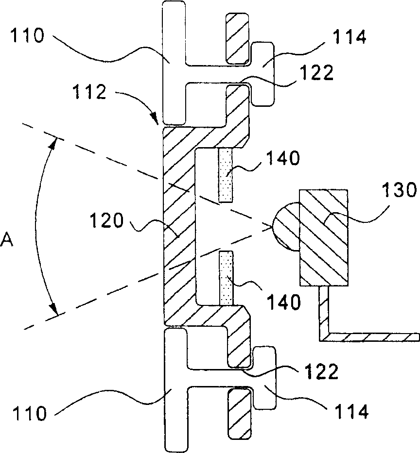
[0026] The invention discloses a remote-control electronic device, which limits the receiving range on the premise of having the least impact on the appearance design, so as to reduce noise and further improve the remote-control performance. The present invention will be described in detail below with reference to the accompanying drawings.

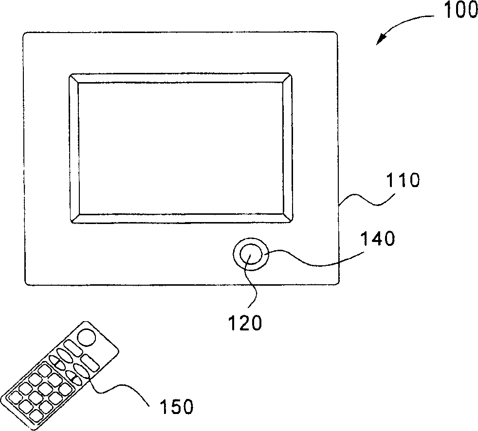
[0027] refer to figure 1 and figure 2 , is a remote control electronic device 100 according to an embodiment of the present invention, which can be any device equipped with a remote control function, such as household electronic products such as TVs, stereos, and VCRs. Take the remote control electronic device 100 as an example, but the implementation of the present invention is not limited thereto. The remote control electronic device 100 includes a housing 110 , a filter component 120 , a sensor 130 , and a shielding component 140 . The casing 110 forms an opening 112 . Housing 110 may be formed using conventional molding materials...


PUM


Abstract

An electronic unit of remote control type is prepared as setting an opening on shell and embedding light filtering component in said opening on shell, setting transducer in shell and using it to receive light signal filtered by light filtering component, setting a blanketing component in front of transducer and using it to define out receiving scope of transducer to receive light signal.

Description

technical field [0001] The present invention relates to a remote-controlled electronic device, in particular to a remote-controlled electronic device capable of defining a signal receiving range. Background technique [0002] With the advancement of technology, the convenience of life has also been continuously improved. Nowadays, many electronic products have the function of remote control. Remote control electronic products are usually equipped with a remote control to send signals to the sensor on the host, and the sensor responds according to the received signal to achieve the effect of remote control of the electronic product. Therefore, how much the sensor receives the signal from the remote control determines how well it responds to the remote control. [0003] The signal sent by the remote controller is generally an optical signal of a specific band, such as a signal of an infrared band. The sensor is designed to respond only to signals in this band. Therefore, i...

Claims


Application Information

Patent Timeline
Patent Type & Authority Applications(China)
IPC IPC(8): G08C23/04G12B9/00
Inventor 游士弘
Owner AU OPTRONICS CORP
Features
  • R&D
  • Intellectual Property
  • Life Sciences
  • Materials
  • Tech Scout
  • Unparalleled Data Quality
  • Higher Quality Content
  • 60% Fewer Hallucinations
Learn More