
Comprehensive test instrument for performance of accoustic material
A comprehensive tester and acoustic material technology, applied in scientific instruments, analytical materials, material analysis using sonic/ultrasonic/infrasonic waves, etc., can solve the problems of low test efficiency, complex data processing process, accuracy dependence, etc., to improve the market. Competitiveness and enterprise benefits, broad application prospects, and the effect of fast debugging
- Summary
- Abstract
- Description
- Claims
- Application Information
AI Technical Summary
Problems solved by technology
Method used
Image

Examples
Embodiment Construction
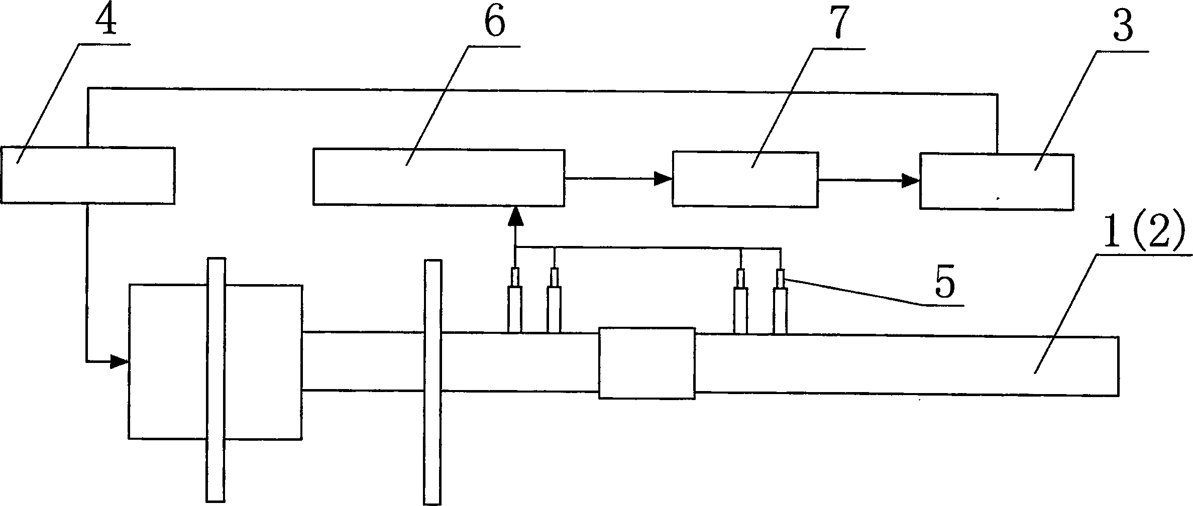
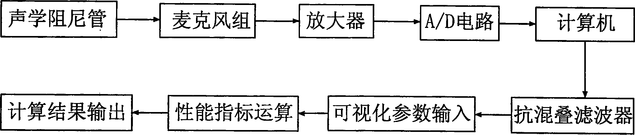
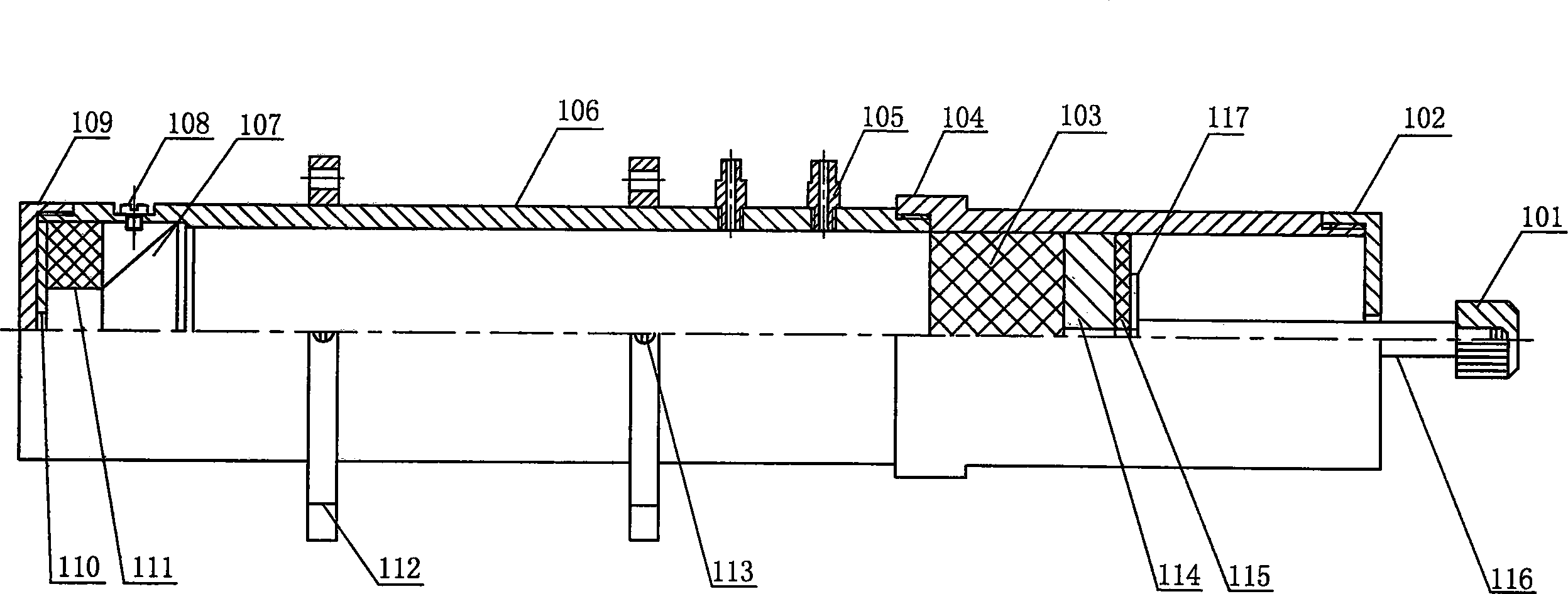
[0016] Such as Figure 1 ~ Figure 4 As shown, the acoustic material performance comprehensive tester is composed of a computer 3 for processing collected data, a double-microphone standing wave tube 1 , a four-microphone standing wave tube 2 , and a four-microphone group 5 . Described double-microphone standing wave tube 1 is made up of the front standing wave tube 106 and the rear standing wave tube 104 connected by thread, the front end cover 109 installed on the front standing wave tube 106, and the front end cover 109 that is located at the front standing wave tube 106 front. Speaker 107 and BNC interface 108, front pad 110 and ring pad 111 placed between front end cover 109 and speaker 107, two microphone clamps 105 installed at the rear of front standing wave tube 106, mounted on rear standing wave tube The piston rod support cover 102 at the 106 rear end, the piston rod 116 passing through the piston rod support cover 102 and located in the rear pipe 104, the piston 114...
PUM
 Abstract
Description
Claims
Application Information