Check patentability & draft patents in minutes with Patsnap Eureka AI!

Light mould member for cast-in-situ concrete

A technology of cast-in-place concrete and components, which is applied to building components, building structures, floor slabs, etc., can solve the problems of affecting the appearance quality of the floor and ceiling, the bottom surface is prone to breakage and cracking, and the damage rate of lightweight tire mold components is high. To achieve the effect of convenient handling and construction, high strength and rigidity, and excellent anti-vibration performance

Inactive Publication Date: 2007-04-11
湖南邱则有专利战略策划有限公司
View PDF3 Cites 0 Cited by
  • Summary
  • Abstract
  • Description
  • Claims
  • Application Information

AI Technical Summary

Problems solved by technology

The above-mentioned solid cast-in-place concrete light-weight tire mold members are used in cast-in-place concrete floors. They are both formwork members and prefabricated filling members. They have the characteristics of simple structure, easy manufacture, and low cost. During the process of handling and construction, the bottom surface is prone to breakage and cracking. Therefore, the damage rate of the lightweight tire mold component is high, and the handling and construction are inconvenient, which increases the construction cost. In addition, if the bottom surface of the lightweight tire mold component and the existing If the bottom surface of the pouring concrete rib is flush and exposed to the ceiling, cracks will easily occur during long-term use, which will affect the appearance quality of the floor ceiling. Therefore, the development of a new type of lightweight tire mold member for cast-in-place concrete has urgent need

Method used


Image

  • Light mould member for cast-in-situ concrete
  • Light mould member for cast-in-situ concrete
  • Light mould member for cast-in-situ concrete

Examples


Embodiment Construction

[0044] The present invention will be further described below in conjunction with the accompanying drawings and embodiments.

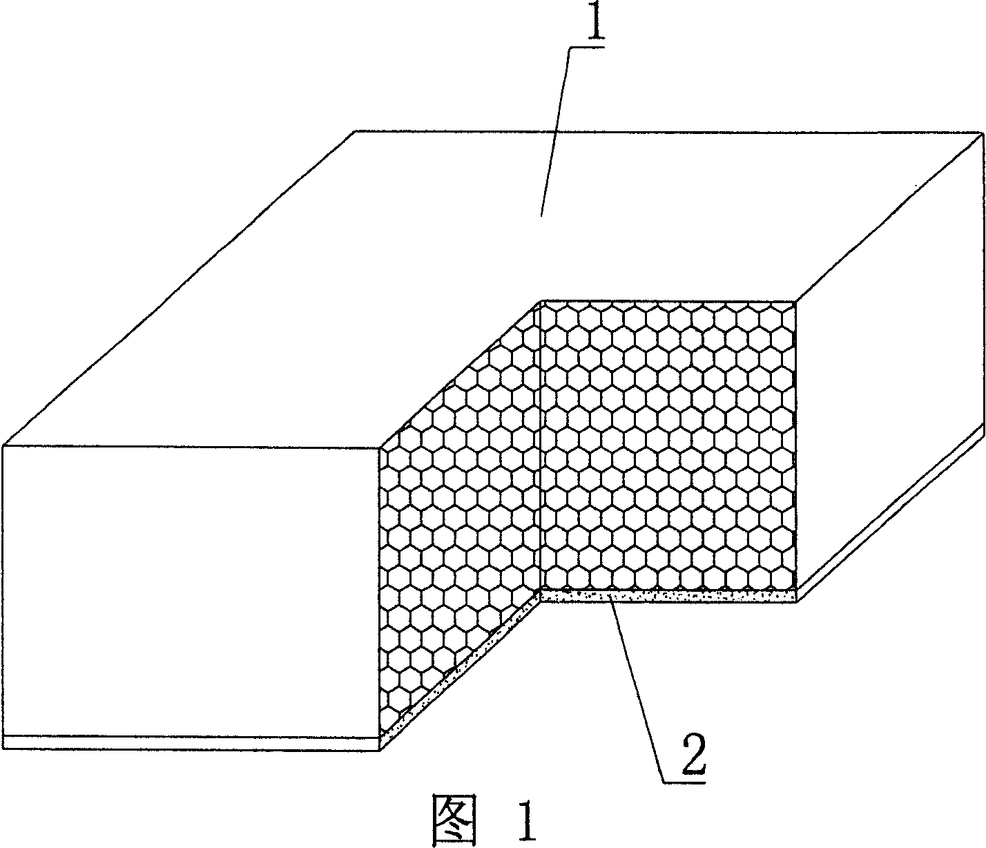
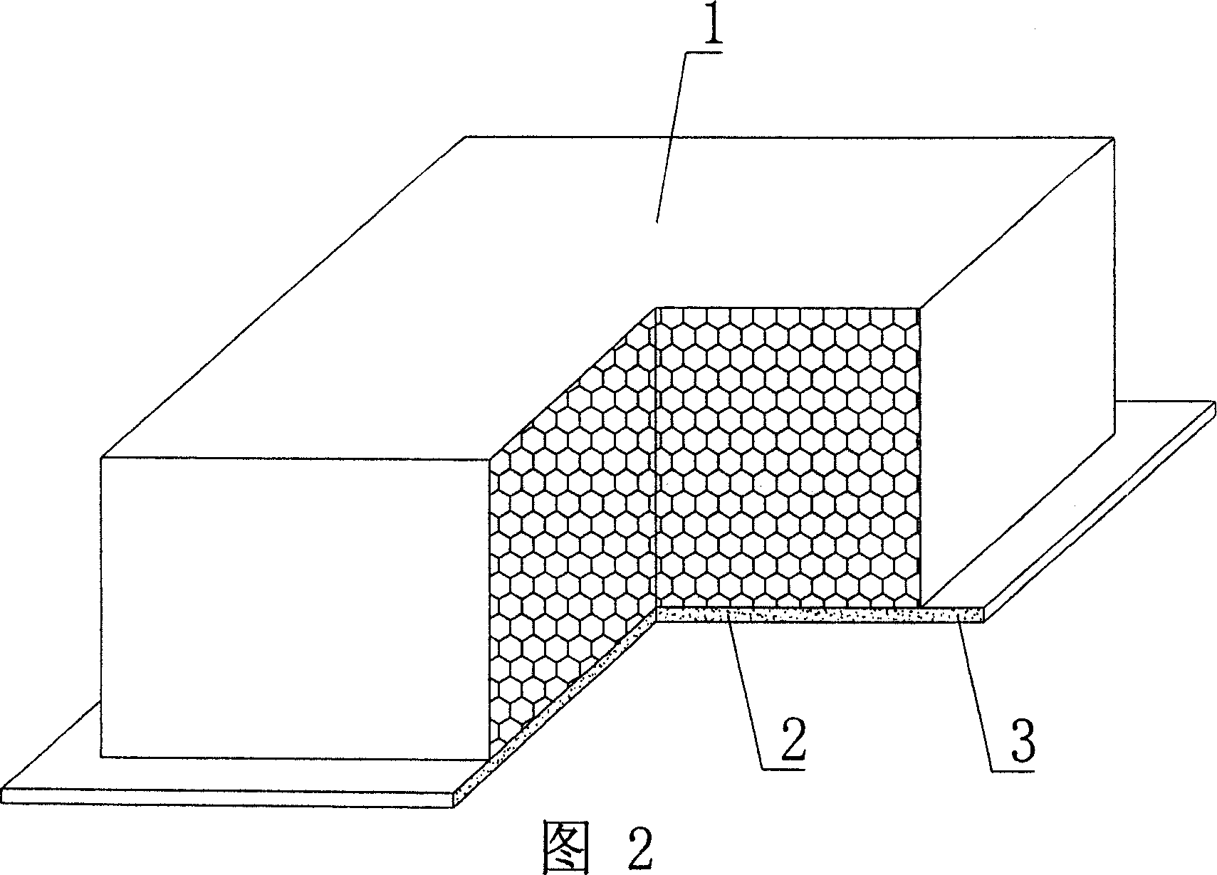
[0045] As shown in the accompanying drawings, the present invention includes a polyhedral solid lightweight material component 1, which is characterized in that it also includes a bottom plate 2, the polyhedral solid lightweight material component 1 is connected to the bottom plate 2 to form a whole, and the bottom plate 2 is a straight strip-shaped bottom plate, At least two polyhedron solid lightweight material members 1 are arranged in parallel and spaced apart in a line on the elongated longitudinal bottom plate 2 , supported by braces 21 at intervals. Fig. 1 is a schematic structural diagram of Embodiment 1 of the present invention. In the accompanying drawings, 1 is a polyhedral solid lightweight material member, and 2 is a base plate. In the following drawings, those with the same number have the same description. As shown in Fig. 1, the polyhed...


PUM


Abstract

The light mold member for in-situ cast concrete includes one polyhedral solid light material member, and features that at least two polyhedral solid light material members are arranged on and connected to one longitudinal bottom slab with supporting parts in between. The present invention is suitable for use in in-situ cast or pre-stressed reinforced concrete floor slab, roof, wall, foundation slab and hollow bridge.

Description

[0001] This application is a divisional application of an invention patent application with an application date of September 15, 2003, an application number of 03157898.5, and a title of "A Lightweight Tire Mold Member for Cast-in-situ Concrete". (1) Technical field [0002] The invention relates to a lightweight tire mold component for cast-in-place concrete. (2) Background technology [0003] At present, the cast-in-place concrete floor is a widely used floor structure. The lightweight permanent tire mold filled in it has various hollow tubes and boxes, and the boxes are hollow or solid. For example, the patent No. ZL00203695.9 applied by Liang Jun, Shijiazhuang City, Hebei Province on February 23, 2000, is called the utility model patent of "combined concrete concealed rib floor cover", and a formwork member is disclosed in its specification sheet. It can be solid or hollow, and its shape can be made into rectangle, circle, polygon and other shapes according to design req...

Claims


Application Information

Patent Timeline
Patent Type & Authority Applications(China)
IPC IPC(8): E04B5/18E04B5/36
Inventor 邱则有
Owner 湖南邱则有专利战略策划有限公司
Features
  • R&D
  • Intellectual Property
  • Life Sciences
  • Materials
  • Tech Scout
  • Unparalleled Data Quality
  • Higher Quality Content
  • 60% Fewer Hallucinations
Learn More