Thin wall metal casing plastic composite pipe and its producing method
A metal shell, plastic parts technology, applied in the direction of pipe elements, pipes/pipe joints/pipe fittings, pipes, etc., can solve the problems of unfavorable mass production, unstable quality, low efficiency, etc. Low, high welding efficiency
- Summary
- Abstract
- Description
- Claims
- Application Information
AI Technical Summary
Problems solved by technology
Method used
Image

Examples
Embodiment Construction
[0020] Below, the present invention is described in further detail in conjunction with accompanying drawing and specific embodiment:
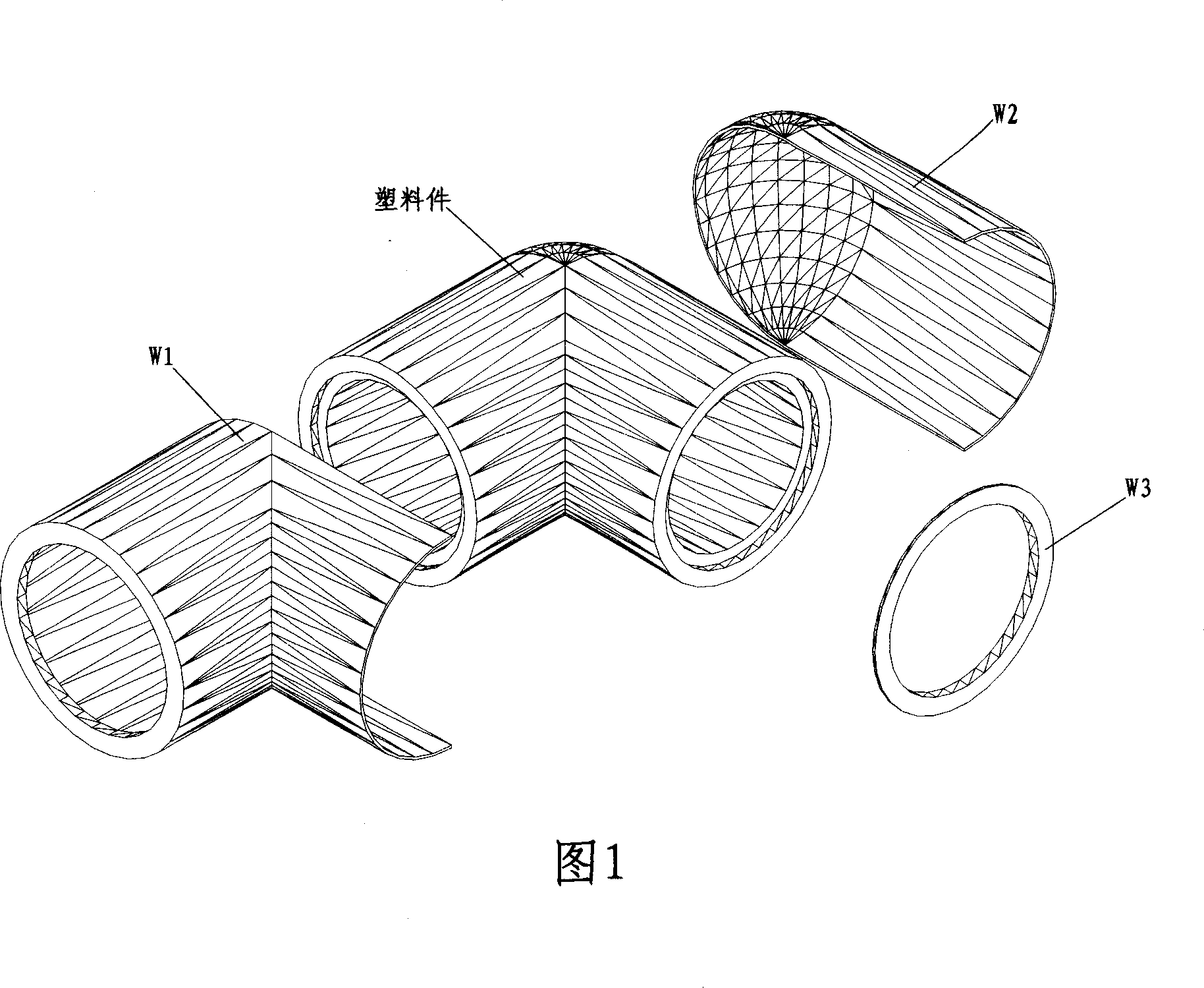
[0021] Figure 1: The elbow is composed of plastic parts and a metal shell, and the elbow shell is composed of three parts with different shapes - W1, W2, and W3. W1 is composed of a tube with one end turned inward twice and a half tube cut along the axis; W2 is composed of a half tube cut along the axis and a 1 / 4 spherical shell; W3 is a circle Disk, the hole in the middle of the disk has a flange.
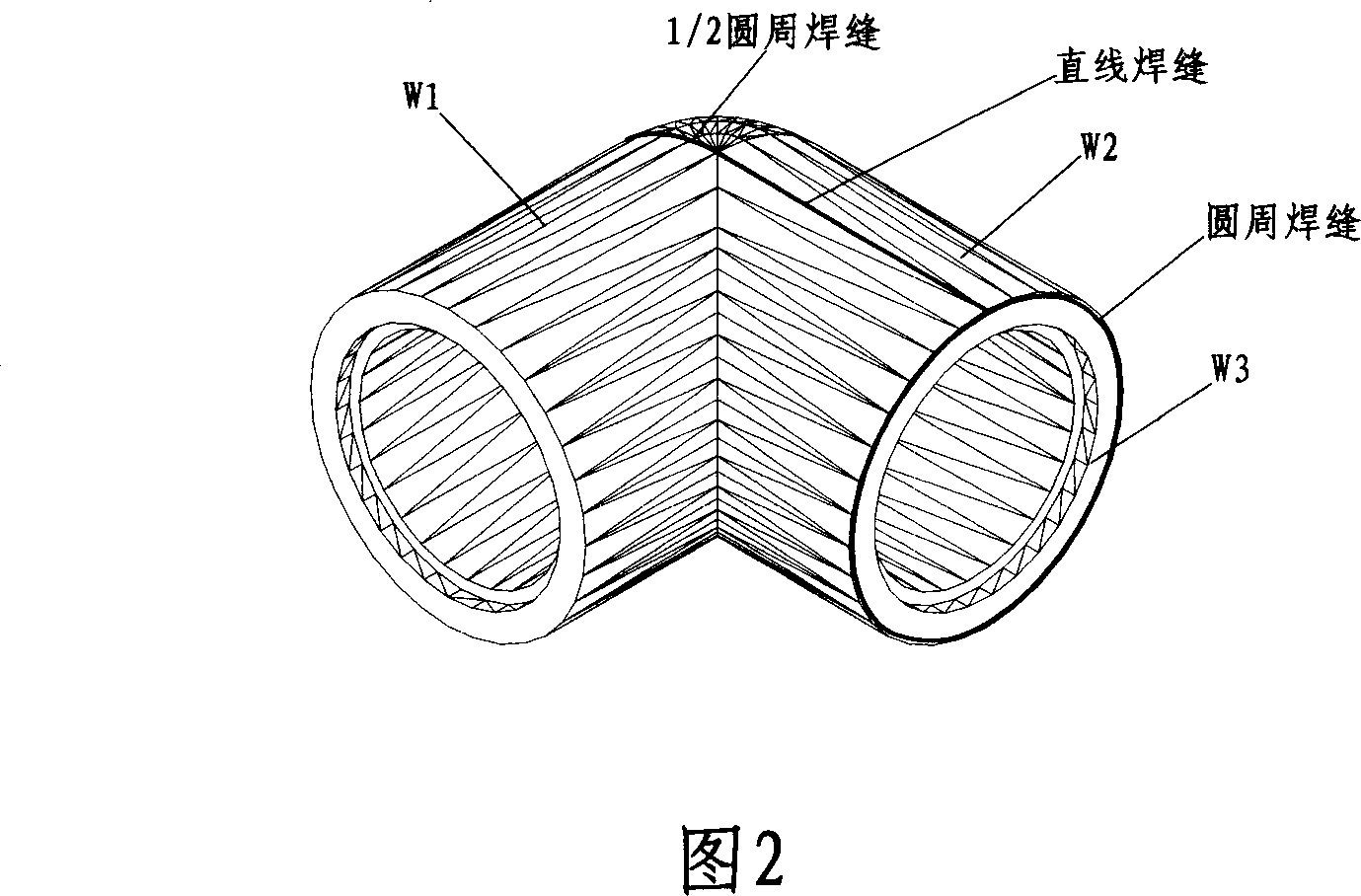
[0022] Figure 2: When W1, W2, and W3 are welded as a whole, there are two straight-line welds and a 1 / 2 circular weld between W1 and W2, and a circular weld between W3 and W1W2.
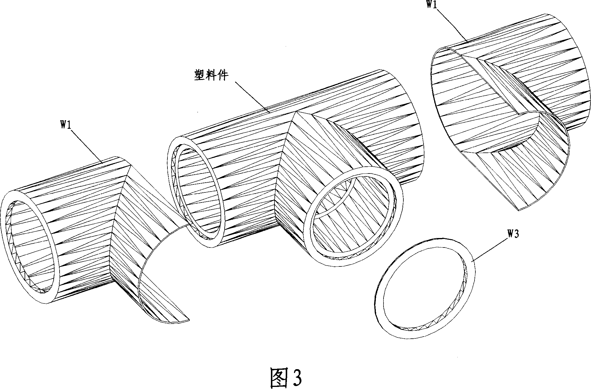
[0023] Figure 3: The tee is composed of plastic parts and a metal shell, and the tee shell is composed of three parts - two W1s and one W3.
[0024] Figure 4: When two W1s and one W3 are welded into a whole, there are two sections of straight line welds and 1 / 2 circular...
PUM
 Abstract
Description
Claims
Application Information
 - Generate Ideas
- Intellectual Property
- Life Sciences
- Materials
- Tech Scout
- Unparalleled Data Quality
- Higher Quality Content
- 60% Fewer Hallucinations
Browse by: Latest US Patents, China's latest patents, Technical Efficacy Thesaurus, Application Domain, Technology Topic, Popular Technical Reports.
© 2025 PatSnap. All rights reserved.Legal|Privacy policy|Modern Slavery Act Transparency Statement|Sitemap|About US| Contact US: help@patsnap.com