Engine control device

A control device, engine technology, applied in the direction of engine control, machine/engine, electrical control, etc., to prevent discomfort

Inactive Publication Date: 2007-05-16
HONDA MOTOR CO LTD
View PDF1 Cites 1 Cited by
  • Summary
  • Abstract
  • Description
  • Claims
  • Application Information

AI Technical Summary

Problems solved by technology

[0005] However, in the technique of Patent Document 1, when the occupant adjusts the idling speed to a speed equal to or substantially equal to the predetermined speed, the engine speed may be repeatedly increased or decreased by increasing or decreasing the engine speed near the predetermined speed. Switching between the ope

Method used


Image

  • Engine control device
  • Engine control device
  • Engine control device

Examples


Example Embodiment

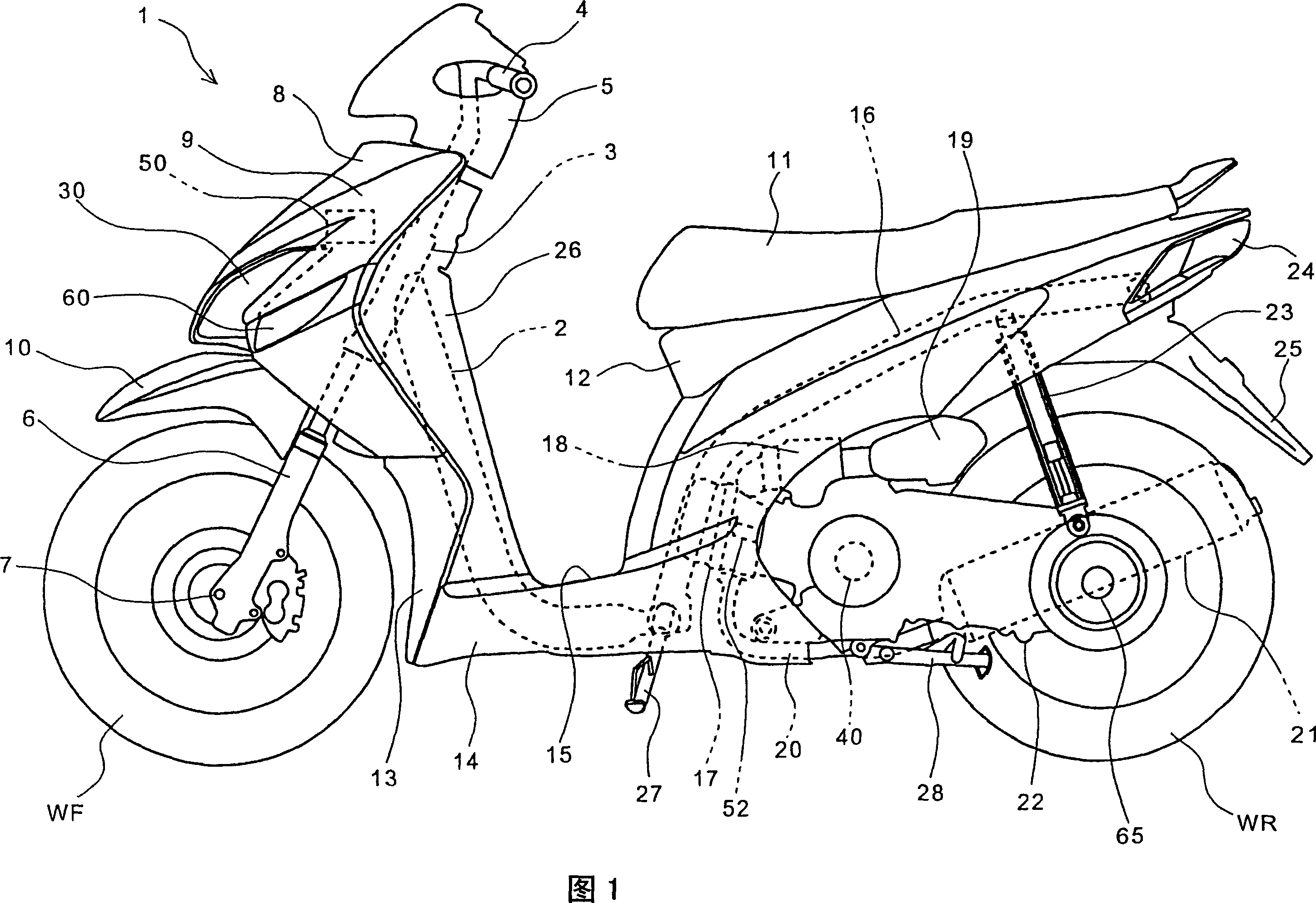
[0020] Hereinafter, the preferred embodiments of the present invention will be described in detail with reference to the accompanying drawings. Fig. 1 is a side view of an embodiment of a motorcycle to which the present invention is applied. The motorcycle 1 is a scooter equipped with a vibration-proof power unit incorporating a continuously variable transmission. A pair of left and right front forks 6 are pivotally supported on a head pipe 3 fixedly connected to a main frame 2 serving as a vehicle frame, and a front wheel WF is pivotally supported on an axle 7 at the lower end thereof. The front fork 6 can be steered by the handlebar 4 protruding from the handlebar cover 5 to the left and right in the vehicle width direction, and the front fender 10 covering the top of the front wheel WF is steered integrally with the front fork 6 . On the front cover 9 serving as a vehicle body cover disposed above the front fender 10 , a left and right double lamp type headlamp unit 60 and...


PUM


Abstract

The present invention provides an engine control device which stops the engine under the rated conditions and prevents the continuous switch sound caused by the auto-decompression device. In the engine control device having the auto-decompression device for the centrifuge, when the rotate speed of the engine exceeds the second specified speed (Nel) (such as 1000 rpm) and rotates for five circles, the device is moved to the igniting stop control mode. In the igniting stop control mode, when the speed does achieve the specified speed (Ne2) lower than the specified basic idling speed, such as 999 rpm, and rotates for 20 circles, the igniting stop control part (505) sends out the igniting stop command to the igniting apparatus control part (503) and stops the engine fast. The specified speed (Ne2) is set as the same or about and about to the action switch rotate speed of the auto-decompression device, to prevent the occupants adjusting downwards to the vicinity of the rotate speed (Nne2) to generate the continuous switch sound for the auto-decompression device.

Description

technical field [0001] The present invention relates to an engine control device, in particular to an engine control device which stops the engine under specified conditions and prevents an automatic decompression device from producing continuous switching sounds. Background technique [0002] Conventionally, there is known a decompression (decompression) device that reduces engine torque by releasing compressed air in a cylinder when starting an engine, and reduces starting operation force caused by backlash or the like. [0003] Patent Document 1 discloses an automatic decompression device in which a centrifugal mechanism that switches the operating state of the decompression device when a predetermined centrifugal force is applied is attached to an end portion of an exhaust-side camshaft. This automatic decompression device operates, for example, a decompression mechanism that does not completely close the exhaust side valve in the compression stroke at a predetermined en...

Claims


Application Information

Patent Timeline
IPC IPC(8): F02D17/00F02D29/02F02D45/00
Inventor 若山浩史滨田明广
Owner HONDA MOTOR CO LTD
Why Eureka
Try Eureka