A buffer switching power supply

A switching power supply and circuit technology, applied in the power supply field, can solve the problems of high voltage, LED lamp string damage, line burnout, etc., and achieve the effect of suppressing surge impact and prolonging service life.

Inactive Publication Date: 2010-04-21
HE SHAN LIDE ELECTRONICS ENTERPRISE CO LTD
View PDF4 Cites 0 Cited by
  • Summary
  • Abstract
  • Description
  • Claims
  • Application Information

AI Technical Summary

Problems solved by technology

For 12V or 24V LED lamps or light string circuits, there will generally be a large voltage between the lines. When the lamp is lit, the sudden excessive current will cause the circuit to burn out, or directly cause the LED lamp or It's the light string that's broken

Method used


Image

  • A buffer switching power supply
  • A buffer switching power supply
  • A buffer switching power supply

Examples


Embodiment Construction

[0015] The content of a buffer switching power supply of the present invention will be further described below in conjunction with the accompanying drawings and embodiments:

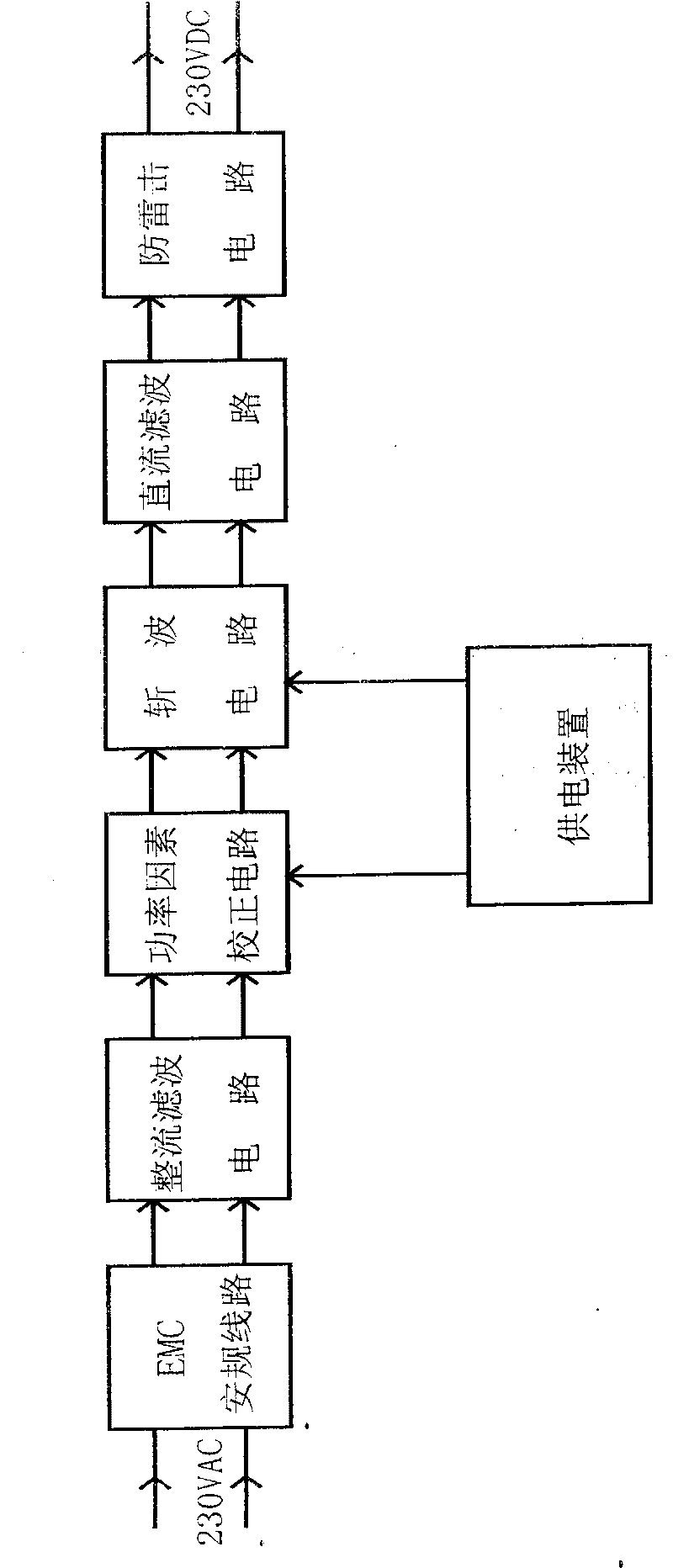
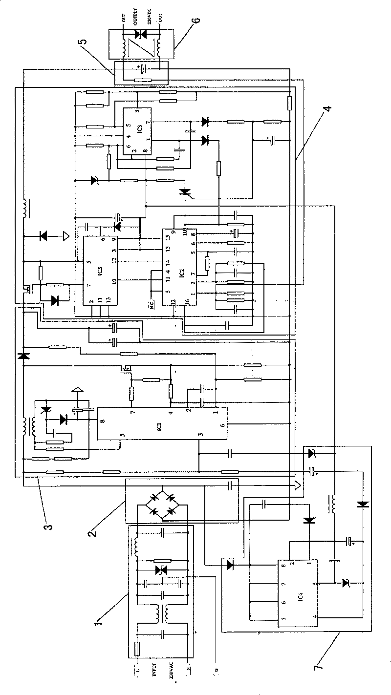
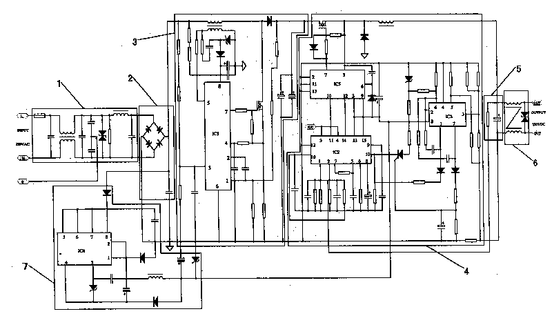
[0016] refer to Figure 1 , the present invention is a buffer switching power supply, comprising an electromagnetic compatibility (EMC) safety circuit 1 connected to a 230V alternating current, and a bridge rectifier filter circuit receiving the output signal of the electromagnetic compatibility (EMC) safety circuit 1 2. A power factor correction (PFC) circuit 3 that receives the output signal of the bridge rectifier filter circuit 2 and increases the voltage and power, and a chopper circuit that receives the power factor correction (PFC) circuit 3 and outputs a high voltage signal and reduces the voltage 4. A DC filter circuit 5 that receives the output signal of the chopper circuit 4 and performs pulsation filtering, a lightning protection circuit 6 that ensures the safe use of the line, and a power fa...


PUM


Abstract

The invention relates to a buffer switch power source, wherein it uses chopper circuit via pulse width control chip to control the connect time of high-pulse of transistor in one period; when the connect time is short, and the pulse width is narrow, the voltage average values at two ends of load are lower; when the connect voltage is long, and the pulse width is wide, the average voltage value ishigher; when the connect time is prolonged, and the pulse width is widened, the voltage average value at two ends of load are increased, the relative lamps will be lightened more; and since it uses power factor correct circuit to respond the output result of alternative-current filter circuit, the output power factor is improved, and the surge impact of LED lamp is restrained, therefore, their service lives are increased.

Description

Technical field [0001] The invention relates to a power supply for a decorative lamp string or a lighting fixture, in particular to a buffer switching power supply applied in the field of LEDs. Background technique [0002] At present, most of the power supply for LED decorative light strings or lighting fixtures use 220V mains power to directly obtain 12V or 24V stable DC power through transformers, rectification, filtering and buffering. However, there are obvious peak and trough periods in electricity consumption in major and medium-sized cities in my country, and the voltage changes in the peak and trough periods of electricity consumption in urban areas are more obvious. In the low valley period, the current in the power supply line is relatively small at this time, the line loss decreases, and the voltage increases accordingly. For 12V or 24V LED lamps or light string circuits, there will generally be a large voltage between the lines. When the lamp is lit, the sudden ...

Claims


Application Information

Patent Timeline
Patent Type & Authority Patents(China)
IPC IPC(8): H02M3/155H02M3/156H05B37/02
CPCY02B20/42Y02B20/40
Inventor 樊邦弘
Owner HE SHAN LIDE ELECTRONICS ENTERPRISE CO LTD
Why Eureka
Try Eureka