Check patentability & draft patents in minutes with Patsnap Eureka AI!

Wireless power receiver for adjusting magnitude of wireless power

a wireless power receiver and wireless power technology, applied in the direction of inductance, battery data exchange, transportation and packaging, etc., can solve the problems of insufficient charging, inability to properly charge, and difficulty in implementing into the conventional method the wireless power receiver

Active Publication Date: 2018-09-04
SAMSUNG ELECTRONICS CO LTD +1
View PDF20 Cites 3 Cited by
  • Summary
  • Abstract
  • Description
  • Claims
  • Application Information

AI Technical Summary

Benefits of technology

The solution enables a more compact and efficient wireless power receiver that maintains high output performance, reduces device size, and improves reliability by controlling power delivery through switching, facilitating better integration in mobile devices.

Problems solved by technology

However, when using such a contact charging method, the contacting terminals are susceptible to contamination by dirt because they extend outward, thus suffering from inappropriate charging, and they may not be properly charged when exposed to moisture.
However, since the DC-to-DC converter must use a bulky passive element, it is difficult to implement into the conventional method the wireless power receiver that satisfies both compactness in appearance and high output performance with high efficiency.
Particularly, when the wireless power receiver is implemented in a mobile communication device such as a cell phone, such difficulty detrimentally affects the current trend of lighter and smaller mobile devices.
In addition, the conventional wireless power receiver suffers from having to include an additional capacitor, such as for impedance matching, and an additional Zener diode for protection of the entire device.

Method used


Image

  • Wireless power receiver for adjusting magnitude of wireless power
  • Wireless power receiver for adjusting magnitude of wireless power
  • Wireless power receiver for adjusting magnitude of wireless power

Examples


Embodiment Construction

[0028]Hereinafter, embodiments of the present invention will be described in detail with reference to the accompanying drawings. In the following description, the same or similar elements may be designated by the same reference numerals in different drawings. Further, detailed descriptions of known functions and configurations incorporated herein may be omitted for the sake of clarity and conciseness.

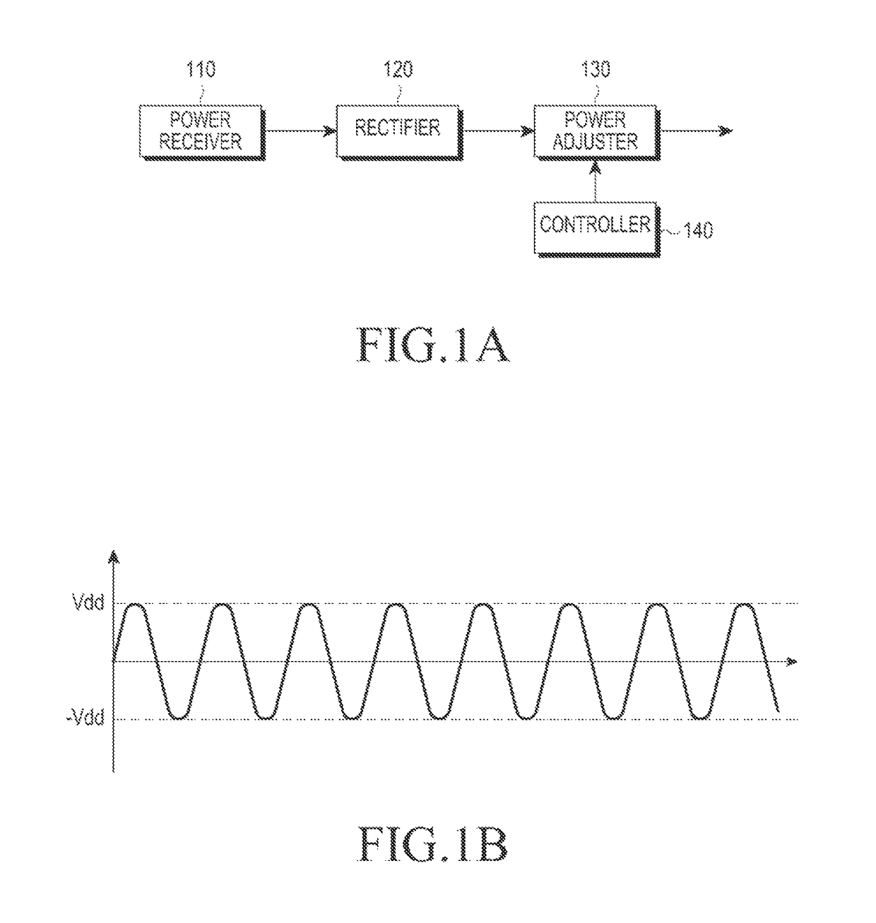
[0029]FIG. 1A illustrates a wireless power receiver, according to an embodiment of the present invention.

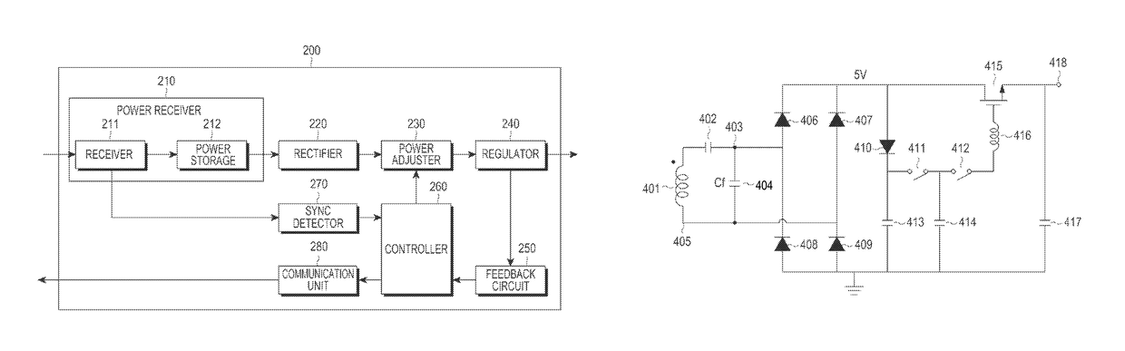
[0030]The wireless power receiver includes a power receiver 110, a rectifier 120, a power adjuster 130, and a controller 140.

[0031]The power receiver 110 receives wireless power supplied by a wireless power supplier. The power may be received based on a resonance method, and thus may be implemented using a loop coil with inductance.

[0032]The power receiver 110 receives the wireless power by resonating with an electromagnetic field produced by the wireless power supplier. When the pow...


PUM

PropertyMeasurementUnit
frequencyaaaaaaaaaa
constant voltageaaaaaaaaaa
frequencyaaaaaaaaaa

Abstract

A wireless power receiver for wirelessly receiving power from a wireless power supplier includes a power receiver for receiving wireless power from the wireless power supplier and storing the wireless power for a first time period, a rectifier connected to the power receiver for rectifying the wireless power, a power adjuster connected to the rectifier and an output end, for adjusting a magnitude of the wireless power by enabling the power receiver to store the wireless power for the first time period and delivering the wireless power to the output end for a second time period, and a controller for determining the first and second time periods.

Description

PRIORITY[0001]This application claims priority under 35 U.S.C. § 119(a) to a Korean Patent Application filed in the Korean Intellectual Property Office on Oct. 19, 2011, and assigned Serial No. 10-2011-0107179, the contents of which are incorporated herein by reference.BACKGROUND OF THE INVENTION[0002]1. Field of the Invention[0003]The present invention relates generally to a wireless power receiver, and more particularly, to a wireless power receiver for wirelessly receiving power based on an electromagnetic resonance method.[0004]2. Description of the Related Art[0005]Mobile terminals, such as cell phones and Personal Digital Assistants (PDAs), are powered by naturally rechargeable batteries, and supply electric energy to the battery using a separate charging device in order to recharge the battery. Typically, the charging device and the battery are electrically connected by a connection of their outer-surface terminals to each other.[0006]However, when using such a contact chargi...

Claims


Application Information

Patent Timeline
Patent Type & Authority Patents(United States)
IPC IPC(8): H01F27/42H02J7/02H02J50/80H02M7/217H02J50/12H02J50/10H01F37/00H01F38/00H04B5/48
CPCH02J50/12H02J7/025H02M7/2176H02J50/80H02J50/10H02J7/00045H02J50/90
Inventor YEO, SUNG-KUCHO, GYU-HYEONGKIM, SE-KIKIM, YU-SUPARK, SE-HOCHOI, JUN-HAN
Owner SAMSUNG ELECTRONICS CO LTD
Features
  • R&D
  • Intellectual Property
  • Life Sciences
  • Materials
  • Tech Scout
  • Unparalleled Data Quality
  • Higher Quality Content
  • 60% Fewer Hallucinations
Learn More