Power converter
a power converter and converter technology, applied in the direction of transformer/inductance details, power conversion systems, inductances with magnetic cores, etc., can solve the problems of adversely affecting the anti-noise performance of the power conversion circuit, increasing the risk of electric noise generation from the electric circuit, etc., to minimize the electrical noise generated, minimize the probability of magnetic coupling, and minimize the effect of electrical noise generated
- Summary
- Abstract
- Description
- Claims
- Application Information
AI Technical Summary
Benefits of technology
Problems solved by technology
Method used
Image


Examples
first embodiment
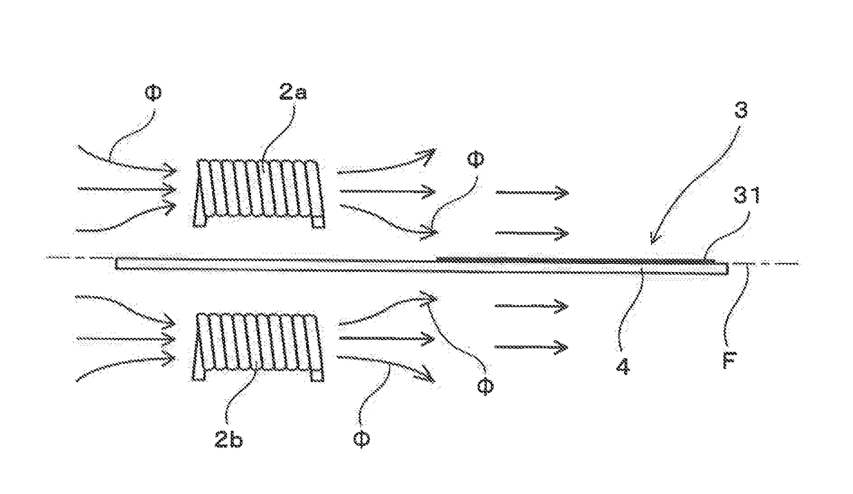
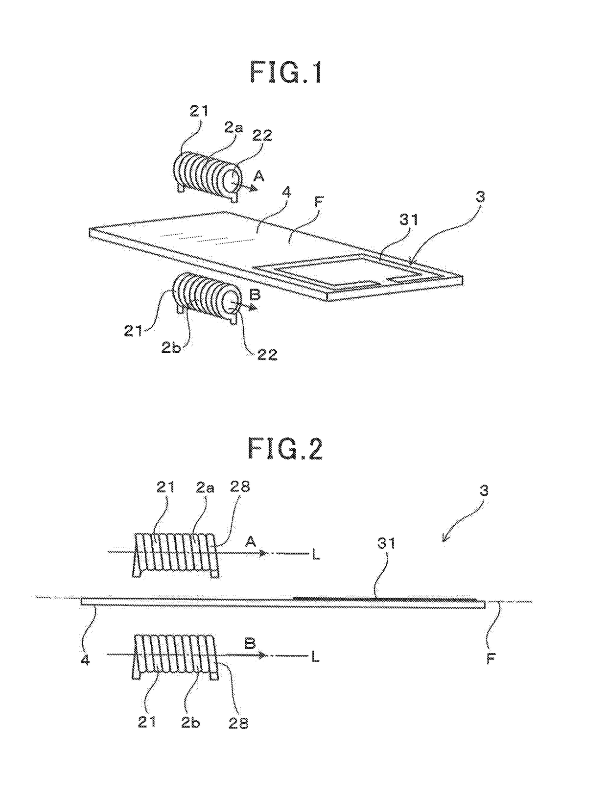
[0025]Referring to the drawings, wherein like reference numbers refer to like parts in several views, particularly to FIGS. 1 to 5, there is shown a power converter according to the first embodiment which may be mounted in automotive vehicles such as electric vehicles or hybrid vehicles. The power converter, as illustrated in FIGS. 1 to 3, includes at least two magnetic devices 2a and 2b equipped with coils 21 and an electrical circuit 3 equipped with a conductor 31 formed on an imaginary plane F disposed between the magnetic devices 2a and 2b.
[0026]In the following discussion, of magnetic fluxes emitted from the coils 21 of the magnetic devices 2a and 2b, vectors of components which are oriented in winding axial directions L (i.e., directions in which axes of turns of conductors 28 of the coils 21 extend) are defined as vectors A and B oriented in an axial direction of the magnetic devices 2a and 2b. The vectors A and B extend substantially parallel to the axial direction of the m...
second embodiment
[0047]A power converter of the second embodiment is, as illustrated in FIG. 8, designed to have the magnetic devices 2a and 2b equipped with the coils 21 which are made of a single conductor 211 (i.e., a single piece of wire). In other words, the coils 21 of the magnetic devices 2a and 2b share the conductor 211 with each other. Other arrangements are identical with those in the first embodiment, and explanation thereof in detail will be omitted here, The same reference numbers, as employed in the first embodiment, will refer to the same parts in embodiments following the first embodiment unless otherwise specified.
[0048]The above arrangements of the coils 21 in the second embodiment enable the magnetic devices 2a and 2b to be designed to emit the magnetic fluxes Φ at the same time, which is effective in avoiding the generation of electrical noise in the electrical circuit 3. The other operations and beneficial advantages of the power converter of this embodiment are the same as tho...
third embodiment
[0049]A power converter of the third embodiment is, as illustrated in FIG. 9, designed to have the magnetic devices 2a and 2b inclined to have the vectors A and B extending at a given angle other than zero to the imaginary plane F. In other words, each of the magnetic devices 2a and 2b is oriented to have a length inclined at a given angle to the imaginary plane F. The angle which each of the vectors A and B makes with the imaginary plane F is preferably selected to be less than or equal to 45°.
[0050]The magnetic devices 2a and 2b of this embodiment are, like in the first embodiment, arranged so that an inner product of vectors derived by projecting the vectors A and B on the imaginary plane F will be positive. The magnetic devices 2a and 2b are also disposed to be mirror image symmetrical with respect to the imaginary plane F. In other words, inclined orientations of the magnetic devices 2a and 2b are directed in opposite directions, Other arrangements are identical with those in t...
PUM
| Property | Measurement | Unit |
|---|---|---|
| angle | aaaaa | aaaaa |
| magnetic fluxes | aaaaa | aaaaa |
| magnetic flux | aaaaa | aaaaa |
Abstract
Description
Claims
Application Information
 - R&D
- Intellectual Property
- Life Sciences
- Materials
- Tech Scout
- Unparalleled Data Quality
- Higher Quality Content
- 60% Fewer Hallucinations
Browse by: Latest US Patents, China's latest patents, Technical Efficacy Thesaurus, Application Domain, Technology Topic, Popular Technical Reports.
© 2025 PatSnap. All rights reserved.Legal|Privacy policy|Modern Slavery Act Transparency Statement|Sitemap|About US| Contact US: help@patsnap.com