Supercharge Your Innovation With Domain-Expert AI Agents!

Switching power supply device

a power supply device and power supply technology, applied in the direction of power conversion systems, dc-dc conversion, instruments, etc., can solve problems such as efficiency drop, and achieve the effect of improving the efficiency of each converter uni

Active Publication Date: 2018-10-23
TDK CORPARATION
View PDF4 Cites 1 Cited by
  • Summary
  • Abstract
  • Description
  • Claims
  • Application Information

AI Technical Summary

Benefits of technology

[0007]With the Class-E converter circuit disclosed in NPTL1, when parallel operation is used to increase the output voltage and improve reliability, during a period where a plurality of Class-E converter circuits connected in parallel operate with a fixed time ratio and a fixed frequency, to have the Class-E converter circuit output a substantially fixed current irrespective of the output voltage, a current balancing circuit such as that disclosed in PTL1 mentioned above is unnecessary.
[0011]The present invention was conceived in view of the problem described above and has a principal object of providing a switching power supply device that is capable of improved efficiency while having a plurality of converter units connected in parallel to increase the output power.
[0013]In this way, the control unit repeatedly executes the first driving control and the second driving control over the converter units while adjusting the output power by increasing and decreasing the driven number of converter units. By doing so, compared to a conventional switching power supply device that performs driving control that simultaneously drives all of the converter units and driving control that simultaneously stops all of the converter units in all of the load states, it is possible, while maintaining the output power in the heavy load state, to reduce the number of converter units subjected to driving control in a lighter load state, which makes it possible to improve efficiency.
[0015]By doing so, it is possible to smoothly transition to the steady-state operation in the changed-to load state, even when there is a big change in the load state. As a result, it is possible to reliably control the variations (or “ripples”) in the DC output voltage Vo to within the reference voltage range.
[0017]By doing so, it is possible to reduce the load for individual converter units, so that it is possible to use small heat sinks.
[0019]By doing so, when each converter unit is constructed as a resonant converter, since it is possible to drive (switch) the respective converter units in driving periods with a fixed time ratio and a fixed frequency that are capable of reliably satisfying the conditions for zero volt switching, it is possible to reliably improve the efficiency of each converter unit.

Problems solved by technology

Since the proportion of the period where there is stable operation with a fixed time ratio and fixed frequency falls, there is the problem of a drop in efficiency.

Method used


Image

  • Switching power supply device
  • Switching power supply device
  • Switching power supply device

Examples


Embodiment Construction

[0041]Preferred embodiments of a switching power supply device will now be described with reference to the attached drawings.

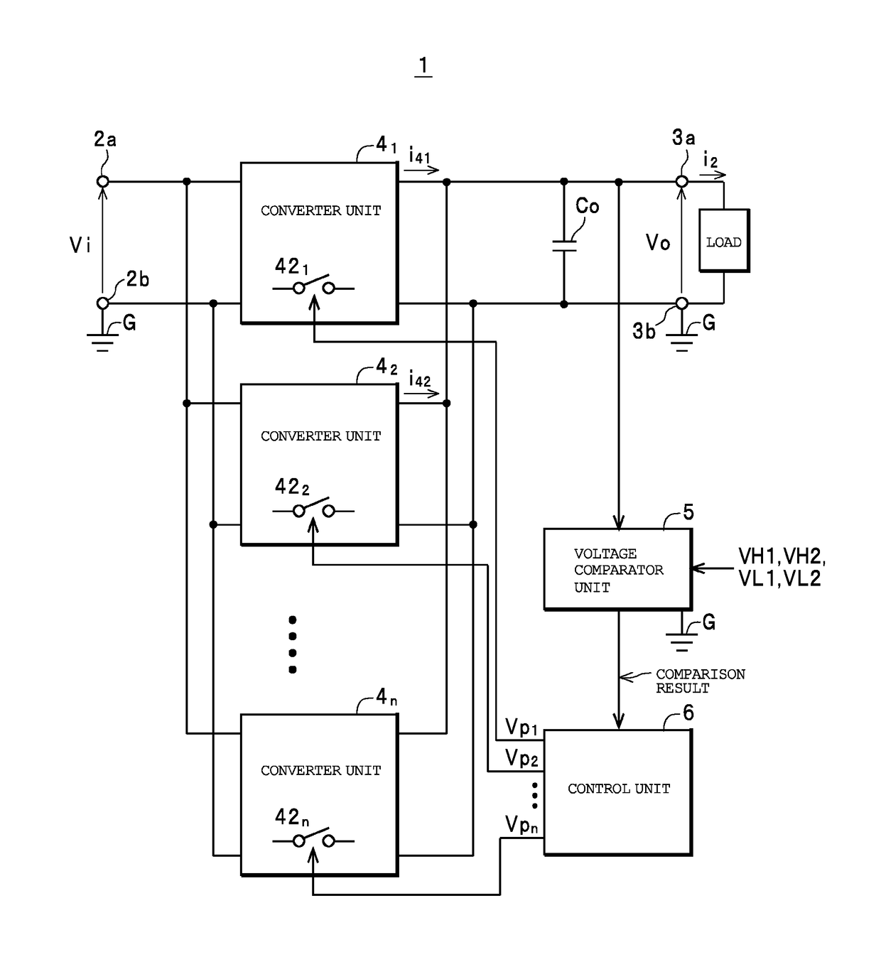
[0042]As depicted in FIG. 1, a switching power supply device 1 as one example of a “switching power supply device” is equipped with a pair of direct current (DC) input terminals 2a and 2b as a “DC input unit”, a pair of DC output terminals 3a and 3b as a “DC output unit”, a plurality (n, where n is an integer of two or higher) of converter units 41, 42, . . . , 4n that are connected in parallel between the pair of DC input terminals 2a and 2b and the pair of DC output terminals 3a and 3b, a voltage comparator unit 5, and a control unit 6, and is configured to be capable of generating a DC output voltage Vo based on a DC input voltage Vi inputted across the DC input terminals 2a and 2b and outputting the DC output voltage Vo from the DC output terminals 3a and 3b to a load. Note that as one example in the present embodiment, the DC input voltage Vi is inputted ...


PUM


Abstract

A switching power supply device generates a DC output voltage based on a DC input voltage, and includes n converter units and a control unit. The control unit executes first driving control that drives k1 (where 0≤k1<n) out of the n converter units when the DC output voltage has risen to an upper limit value of the reference voltage range and second driving control that drives k2 (where k1<k2≤n) out of the n converter units when the DC output voltage has fallen to a lower limit value of the reference voltage range. During the first driving control, if the DC output voltage Vo reaches a first value above the upper limit value, k1 and k2 are decreased by a value k0. During the second driving control, if the DC output voltage Vo reaches a second value below the lower limit value, k1 and k2 are increased by the value k0.

Description

FIELD OF THE INVENTION[0001]The present invention relates to a switching power supply device equipped with a plurality of converter units that are interconnected in parallel.DESCRIPTION OF THE RELATED ART[0002]Due to recent improvements in the performance of power semiconductors and the commercialization of power semiconductors that use compound semiconductors such as GaN and SiC, it has become possible to raise the switching frequency of switching power supply devices, which enables switching power supply devices to be miniaturized and have higher power densities. However, when the power density of a switching power supply device is increased, parasitic inductance present in the wiring and elements becomes problematic. This makes it necessary to use elements, such as surface-mounted elements, that have low parasitic inductance and to mount elements in a compact arrangement to shorten the wiring between them. However, it is typically difficult to increase the output power capacities...

Claims


Application Information

Patent Timeline
Patent Type & Authority Patents(United States)
IPC IPC(8): H02M3/158
CPCH02M3/1584
Inventor MATSUURA, KENLIN, MIN
Owner TDK CORPARATION
Features
  • R&D
  • Intellectual Property
  • Life Sciences
  • Materials
  • Tech Scout
  • Unparalleled Data Quality
  • Higher Quality Content
  • 60% Fewer Hallucinations
Learn More