Shutdown system for a nuclear steam supply system

a technology of nuclear steam supply and shutdown system, which is applied in the direction of steam generation using hot heat carriers, greenhouse gas reduction, nuclear elements, etc., can solve the problems of inability to use frictional heat to heat the water inventory of the reactor during start-up, and the above process for heating the water inventory of the reactor is not available, so as to achieve the effect of improving the shutdown system

Active Publication Date: 2018-10-30
SMR INVENTEC
View PDF17 Cites 2 Cited by
  • Summary
  • Abstract
  • Description
  • Claims
  • Application Information

AI Technical Summary

Benefits of technology

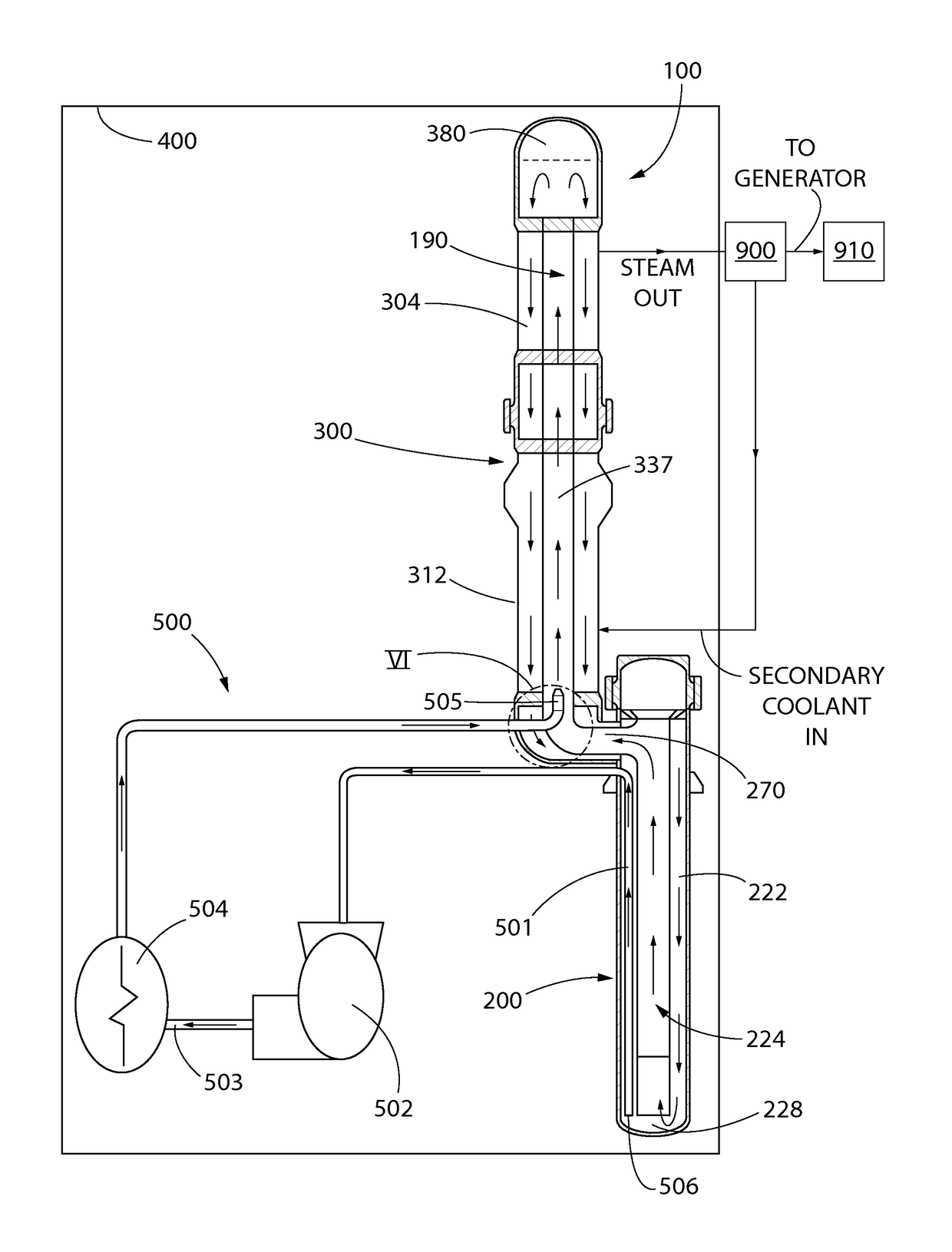
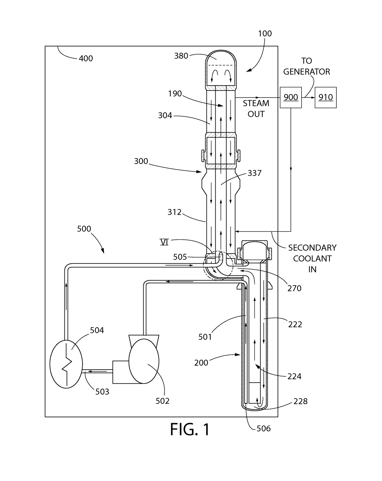
[0007]The present disclosure provides an improved shutdown system for a nuclear steam supply system. The shutdown system may include a primary coolant cooling system and a secondary coolant cooling systems. Both cooling systems may be operated in tandem and cooperation to cool the primary coolant, which in turn removes and rejects residual decay heat produced by the nuclear fuel core during reactor shutdown conditions. In one embodiment, as further described herein, the primary and secondary coolant cooling systems may be operated in sequential stages or phases to gradually and safely bring the reactor from a hot full power state to a cold and shutdown state.

Problems solved by technology

However, during start-up external cooling is disabled so that the frictional heat can be directly transferred to the reactor coolant water, enabling it to reach no-load operating temperature.
The above process for heating the reactor water inventory during start-up is not available in a passively safe nuclear steam supply system.
This is because such a passively safe nuclear steam supply system does not include or require any pumps, and thus the use of the frictional heat is unavailable for heating the reactor water inventory.

Method used


Image

  • Shutdown system for a nuclear steam supply system
  • Shutdown system for a nuclear steam supply system
  • Shutdown system for a nuclear steam supply system

Examples


Embodiment Construction

[0033]The features and benefits of the invention are illustrated and described herein by reference to exemplary embodiments. This description of exemplary embodiments is intended to be read in connection with the accompanying drawings, which are to be considered part of the entire written description. In the description of embodiments disclosed herein, any reference to direction or orientation is merely intended for convenience of description and is not intended in any way to limit the scope of the present invention. Relative terms such as “lower,”“upper,”“horizontal,”“vertical,”, “above,”“below,”“up,”“down,”“top” and “bottom” as well as derivative thereof (e.g., “horizontally,”“downwardly,”“upwardly,” etc.) should be construed to refer to the orientation as then described or as shown in the drawing under discussion. These relative terms are for convenience of description only and do not require that the apparatus be constructed or operated in a particular orientation. Terms such as...


PUM


Abstract

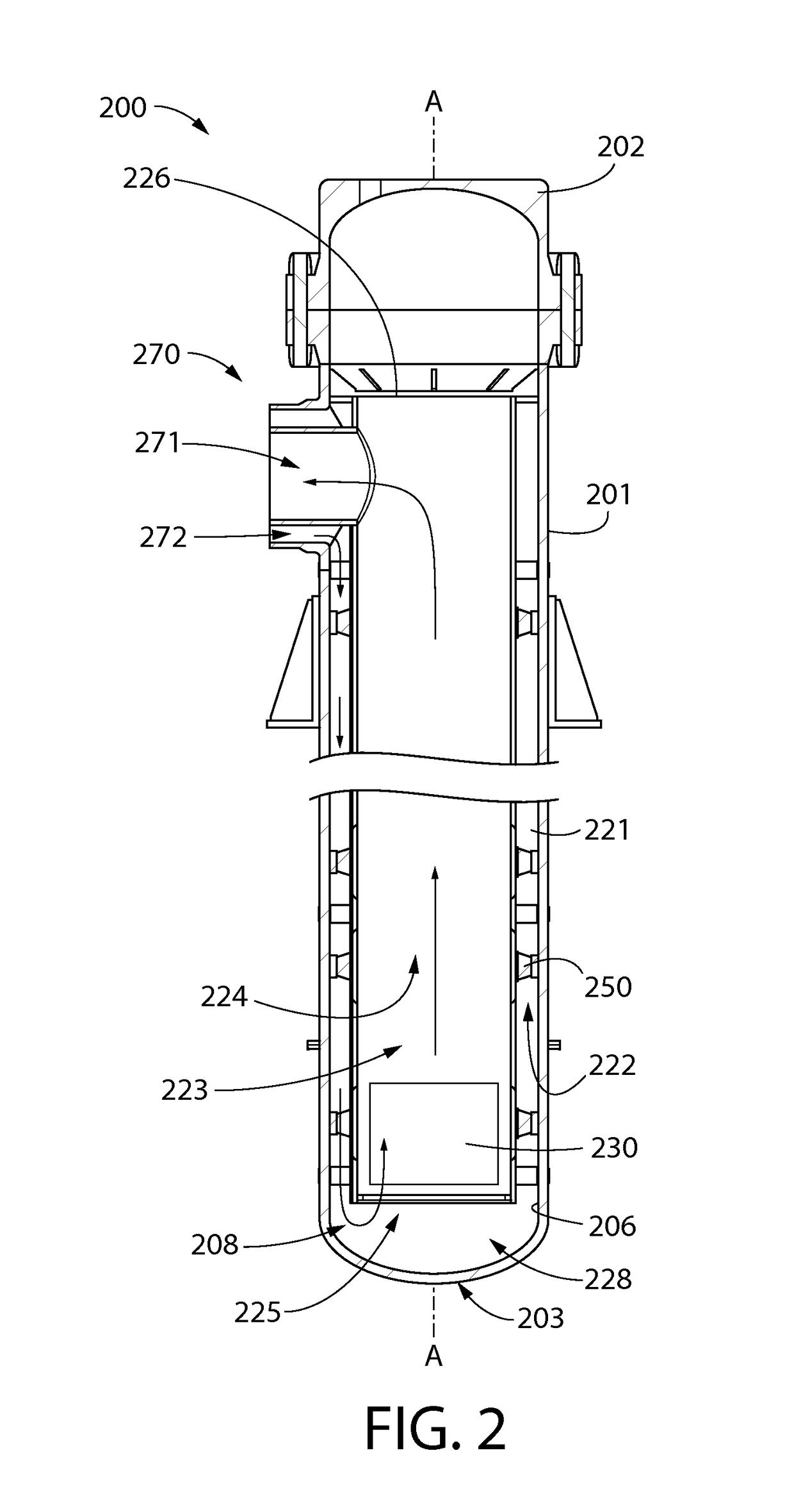
A nuclear steam supply system having a shutdown system for removing residual decay heat generated by a nuclear fuel core. The steam supply system may utilize gravity-driven primary coolant circulation through hydraulic-ally interconnected reactor and steam generating vessels forming the steam supply system. The shutdown system may comprise primary and secondary coolant systems. The primary coolant cooling system may include a jet pump comprising an injection nozzle disposed inside the steam generating vessel A portion of the circulating primary coolant is extracted, pressurized and returned to the steam generating vessel to induce coolant circulation under reactor shutdown conditions. The extracted primary coolant may further be cooled before return to the steam generating vessel in some operating modes. The secondary coolant cooling system includes a pumped and cooled flow circuit operating to circulate and cool the secondary coolant, which in tun extracts heat from and cools the primary coolant.

Description

CROSS-REFERENCE TO RELATED PATENT APPLICATIONS[0001]The present application claims the benefit of PCT International Patent Application No. PCT / US2013 / 063405 filed Oct. 4, 2013, which claims the benefit of U.S. Provisional Patent Application Ser. No. 61 / 709,436 filed Oct. 4, 2012, and is a continuation-in-part of PCT International Patent Application No. PCT / US13 / 54961 filed Aug. 14, 2013, which claims priority to U.S. Provisional Patent Application Ser. No. 61 / 683,021, filed Aug. 14, 2012; the entireties of which are all incorporated herein by reference.FIELD OF THE INVENTION[0002]The present invention relates to nuclear steam supply systems, and more particularly to a shutdown system for a nuclear steam supply system usable for cooling primary and secondary coolant.BACKGROUND OF THE INVENTION[0003]For starting up a nuclear steam supply system in a typical pressurized water reactor (PWR), it is necessary to heat the reactor coolant water to an operating temperature, which is known in...

Claims


Application Information

Patent Timeline
Patent Type & Authority Patents(United States)
IPC IPC(8): G21C15/18G21C1/32F22B1/02G21D3/14G21C15/00G21D1/00G21D1/04
CPCG21C15/182F22B1/023G21C1/32G21C15/00G21D1/006G21D1/04G21D3/14G21C15/18Y02E30/40Y02E30/00Y02E30/30G21C15/243
Inventor SINGH, KRISHNA P.RAJKUMAR, JOSEPH
Owner SMR INVENTEC
Why Eureka
Try Eureka