Check patentability & draft patents in minutes with Patsnap Eureka AI!

Plugged honeycomb structure and plugged honeycomb segment

a honeycomb and structure technology, applied in the direction of machines/engines, separation processes, transportation and packaging, etc., can solve the problems of honeycomb segment breaking, continuous regeneration performance as described above deteriorates, and excessively accumulated pm is suddenly burned

Active Publication Date: 2018-11-06
NGK INSULATORS LTD
View PDF26 Cites 2 Cited by
  • Summary
  • Abstract
  • Description
  • Claims
  • Application Information

AI Technical Summary

Benefits of technology

[0109]Furthermore, the plugged honeycomb segments in the first to the sixth embodiments are configured so that the overall cell arrangement defined by the partition walls is axisymmetric in a cross section orthogonal to the axial direction of the plugged honeycomb segment. Although not illustrated, the plugged honeycomb segment may be configured so that the overall arrangement of the cells defined by the partition walls is not axisymmetric in a cross section orthogonal to the axial direction of the plugged honeycomb segment. In such a plugged honeycomb segment as well, it is configured so that the circumferential region is configured to have an open frontal area that is larger than an open frontal area of the center region in the inflow end face of the honeycomb segment, whereby advantageous effects in the same as those of the plugged honeycomb structure of the first embodiment can be obtained.
[0111]There is no particular limitation on the method for manufacturing the plugged honeycomb structure of the present embodiment shown in FIGS. 1 through 5, and this can be manufactured by the following method, for example. Firstly a kneaded material having plasticity is prepared to manufacture a honeycomb segment. The kneaded material to manufacture a honeycomb segment can be prepared by appropriately adding additives such as a binder and water into a material selected as a raw material powder from the aforementioned materials suitable for honeycomb segment. As the raw material powder, for example, silicon carbide powder may be used. For example, the binder includes methylcellulose or hydroxypropoxylmethylcellulose. Moreover, the additives include a surfactant.
[0112]Next, the thus obtained kneaded material is extruded to prepare a prismatic columnar honeycomb formed body, having partition walls defining a plurality of cells and a segment circumferential wall disposed at the outermost circumference. A plurality of the honeycomb formed bodies is prepared.
[0113]The thus obtained honeycomb formed bodies are dried by microwaves and hot air, for example, and then open ends of the cells are plugged with the same material as the material used for the honeycomb formed bodies to prepare plugging portions. After the plugging portions are prepared, the honeycomb formed bodies may be further dried.
[0114]Next, each of the honeycomb formed bodies with the plugging portions is fired to obtain a plugged honeycomb segment. The firing temperature and the atmosphere for firing depend on the raw materials used, and a person skilled in the art could select an appropriate temperature and atmosphere for firing depending on the selected materials. Next, the plurality of plugged honeycomb segments are mutually bonded by using a bonding material. After the plurality of plugged honeycomb segments are dried and hardened, a circumference is processed to obtain a desirable shape, and then this can provide a plugged honeycomb structure having a segmented structure. The bonding material may include a material prepared by adding a solvent such as water into to a ceramics material to be in a paste form. Since the cells are exposed in the processed surface after the circumference of the plugged honeycomb segments is processed, a circumference coating material may be applied to the processed surface to form the outer wall as shown in FIG. 1. As the circumference coating material, the same material as that of the bonding material can be used.
[0116]Next, the following describes the first embodiment of the plugged honeycomb segment of the present invention. The plugged honeycomb segment of the present embodiment is used for the plugged honeycomb structure of the first embodiment as described above.

Problems solved by technology

However, since less an exhaust gas at high temperatures also flows at the circumferential part of each of the honeycomb segments, the continuous regeneration performance as described above deteriorates, and more PM tends to be accumulated at the circumferential part of each of the honeycomb segments by purifying an exhaust-gas for a long time.
If the PM is accumulated excessively at the circumferential part only, the excessively accumulated PM is burnt suddenly and the honeycomb segment may break in some cases.

Method used


Image

  • Plugged honeycomb structure and plugged honeycomb segment
  • Plugged honeycomb structure and plugged honeycomb segment
  • Plugged honeycomb structure and plugged honeycomb segment

Examples


example 1

[0122]As a ceramic raw material, silicon carbide (SiC) powder and metal silicon (Si) powder were mixed at the mass ratio of 80:20 to prepare a mixed raw material. Hydroxypropylmethylcellulose as a binder, a water absorbable resin as a pore former and further water were added to this mixed raw material to prepare a forming raw material. Then, the obtained forming raw material was kneaded by a kneader to prepare a kneaded material.

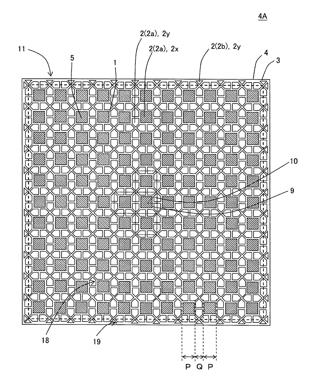
[0123]Next, the obtained kneaded material was formed by a vacuum extruder to prepare sixteen pieces of quadrangular prismatic-columnar honeycomb segments 4 having a repeated pattern 9 including the same cell arrangement as that of the plugged honeycomb segment 4A shown in FIG. 7. Herein, the “same cell arrangement as that of the plugged honeycomb segment 4A shown in FIG. 7” means the arrangement of cells such that eight inflow cells whose cross-sectional shape is a pentagonal shape surround an outflow cell whose cross-sectional shape is a square shape. Then,...

examples 2 to 14

[0132]The plugged honeycomb structures of Examples 2 to 14 were manufactured, in which the design, segment size, thickness of a partition wall, distance P, distance Q, open frontal area of a center region in inflow end face, open frontal area of a circumferential region in an inflow end face, bonding width, and segment circumferential wall thickness were changed as shown in Table 1. The ceramic raw material to prepare the plugged honeycomb segments was prepared in the same manner as in Example 1.

[0133]In Example 2, sixteen pieces of quadrangular prismatic-columnar honeycomb segments 24 having a repeated pattern 29 including the same cell arrangement as that of the plugged honeycomb segment 24A shown in FIG. 10 were prepared. The prepared plugged honeycomb segment included the two kinds of the quadrangular outflow cells 22x and the pentagonal inflow cells 22y at the outermost circumference in the same manner as in the plugged honeycomb segment 24A shown in FIG. 10. The plugged honeyc...


PUM

PropertyMeasurementUnit
thicknessaaaaaaaaaa
thicknessaaaaaaaaaa
mass %aaaaaaaaaa

Abstract

A plugged honeycomb structure includes: a plurality of honeycomb segments, a bonding layer, and plugging portions to plug open ends of cells of the honeycomb segments. The honeycomb segment is configured so that the cells having at least two kinds of different shapes are disposed in a cross section orthogonal to an extension direction of the cells, the honeycomb segment has a center region configured by repeating units to maintain a repeated pattern including cell arrangement in which inflow cells surround an inflow cell, and a circumferential region located at the circumference of the center region, the circumferential region has open frontal area that is larger than open frontal area of the center region at the inflow end face of the honeycomb segment, the segment circumferential wall and the bonding layer have a special range of a thickness.

Description

[0001]The present application is an application based on JP2015-172708 filed on Feb. 9, 2015 with the Japan Patent Office, the entire contents of which are incorporated herein by reference.BACKGROUND OF THE INVENTION[0002]Field of the Invention[0003]The present invention relates to a plugged honeycomb structure and a plugged honeycomb segment. More particularly the present invention relates to a plugged honeycomb structure and a plugged honeycomb segment capable of improving a continuous regeneration performance of a filter to trap a particulate matter when they are used as the filter and so preventing a segregation of a particulate matter in the filter.[0004]Description of the Related Art[0005]In recent years, there has been a demand for the reduction in a fuel consumption of an automobile from the viewpoints of influences on the global environment and resource saving. This leads to a tendency of using internal combustion engines with a good thermal efficiency, such as a direct inj...

Claims


Application Information

Patent Timeline
Patent Type & Authority Patents(United States)
IPC IPC(8): B01D50/00B01D46/24
CPCB01D46/2455B01D46/247B01D46/2459B01D46/2474B01D46/2466B01D2046/2492B01D2046/2481B01D2046/2485F01N3/0222B01D46/2478B01D46/2486B01D46/2484B01D46/2482
Inventor MORI, KAZUYAHIRAKAWA, TOSHIHIRO
Owner NGK INSULATORS LTD
Features
  • R&D
  • Intellectual Property
  • Life Sciences
  • Materials
  • Tech Scout
  • Unparalleled Data Quality
  • Higher Quality Content
  • 60% Fewer Hallucinations
Learn More