Customer bleed air pressure loss reduction
a technology for reducing customer bleed air pressure and reducing the cost of bleed air, which is applied in the direction of efficient propulsion technology, machines/engines, stators, etc., can solve the problems of reducing the efficiency of associated aircraft, unable to provide sufficient air, and raising challenges near the ports, so as to reduce the cross-sectional flow and increase the cross-sectional flow area
- Summary
- Abstract
- Description
- Claims
- Application Information
AI Technical Summary
Benefits of technology
Problems solved by technology
Method used
Image

Examples
embodiment 118
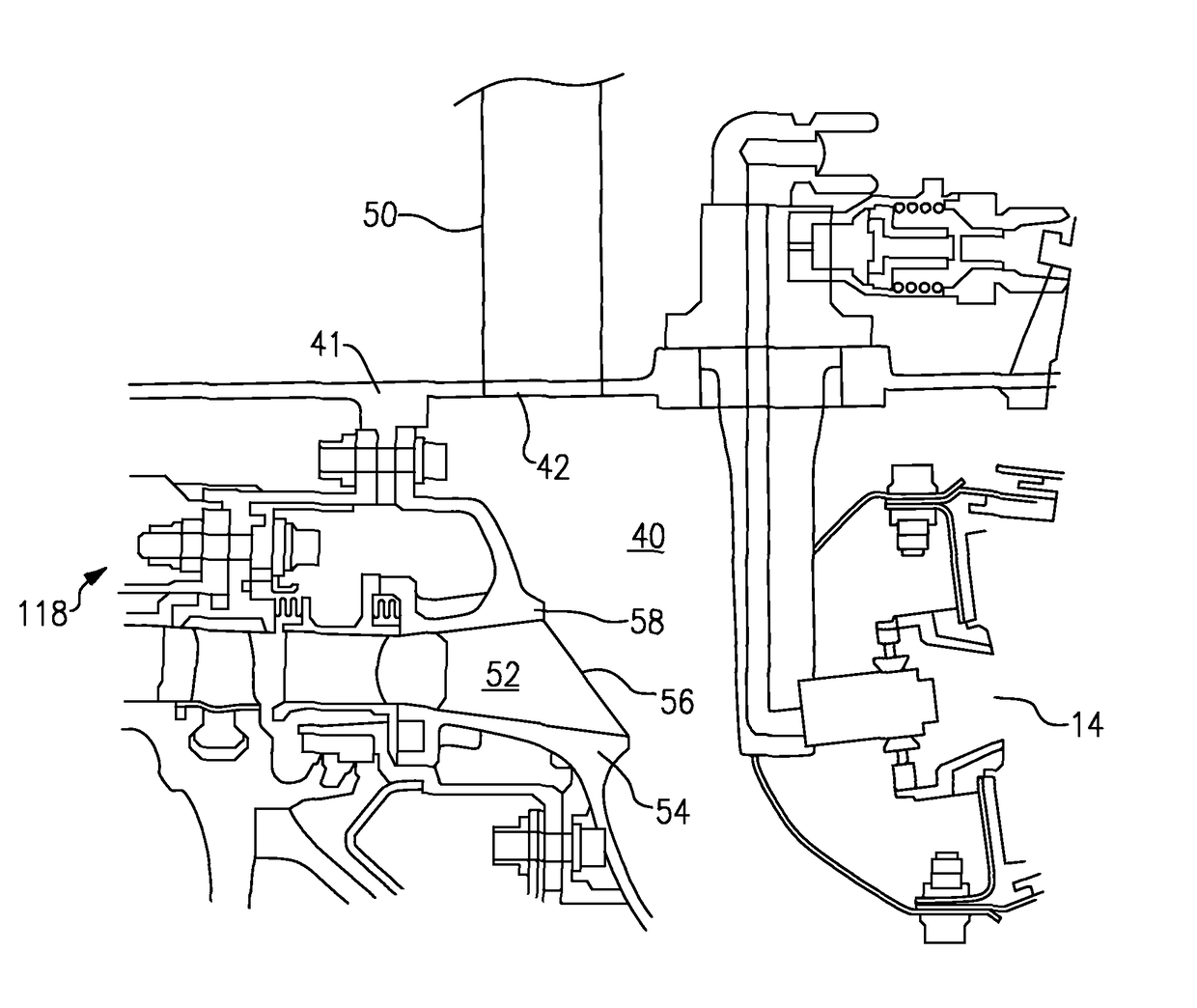
[0044]FIG. 4 shows a diffuser embodiment 118 wherein an outer shroud 58 of the diffuser ends upstream of a radially inner shroud 54. As shown, vanes 56 extend between the shroud walls 54 and 58.
[0045]The duct 50 communicates with an opening 42. Further details of this duct will be disclosed below.
[0046]FIG. 5 shows a portion of the diffuser 118. As shown, the outer shroud is cut upstream, at locations 58 associated with the opening 42, but otherwise extends forwardly 158 to the location of the prior art diffuser as shown, for example, in FIG. 3. In embodiments, there are plural ducts 50 and openings 42, and the cutaway locations 58 are associated with each opening 42.
[0047]Cutting away the diffuser at the areas 58 associated with the opening 42 dramatically reduces pressure loss.
[0048]FIG. 6A shows an arrangement wherein the ports 64 and 66 communicate with a common conduit 62, which then communicates downstream to various uses for air on the aircraft. Ports 64 and 66 are spaced by ...
embodiment 150
[0054]FIG. 7B shows the use of the insert 182 in a somewhat alternative duct embodiment 150. As can be seen from FIG. 7A, the insert and duct in the FIG. 7A embodiment bend at 88, while the FIG. 7B embodiment extends generally linearly.
[0055]As shown in FIG. 7B, an upstream flow cross-sectional area A1 defined between the outer periphery of the insert 182 and the inner periphery of the duct 150 is much smaller than a downstream cross-sectional flow area A2 again defined between the insert and the inner wall of the duct. This creates a venturi effect.
[0056]As can be seen from the FIGS. 7A and 7B, the insert ends at an intermediate location within the ducts 50 or 150, and will end before the outlet 400 of the duct 50, which communicates into other portions of the air supply system.
[0057]FIG. 7C shows features of the FIG. 7A or 7B embodiments wherein insert holders 90 mount the insert within the duct 50. In this embodiment there are three insert holders, each spaced by 120°.
[0058]FIG. ...
PUM
 Abstract
Description
Claims
Application Information
 - R&D
- Intellectual Property
- Life Sciences
- Materials
- Tech Scout
- Unparalleled Data Quality
- Higher Quality Content
- 60% Fewer Hallucinations
Browse by: Latest US Patents, China's latest patents, Technical Efficacy Thesaurus, Application Domain, Technology Topic, Popular Technical Reports.
© 2025 PatSnap. All rights reserved.Legal|Privacy policy|Modern Slavery Act Transparency Statement|Sitemap|About US| Contact US: help@patsnap.com