Modeling device, three-dimensional model generating device, modeling method, and program
a three-dimensional model and generating device technology, applied in the field of modeling devices, three-dimensional model generating devices, modeling methods, programs, etc., can solve the problem of not being able to generate a three-dimensional object model
- Summary
- Abstract
- Description
- Claims
- Application Information
AI Technical Summary
Benefits of technology
Problems solved by technology
Method used
Image

Examples
operation example 1
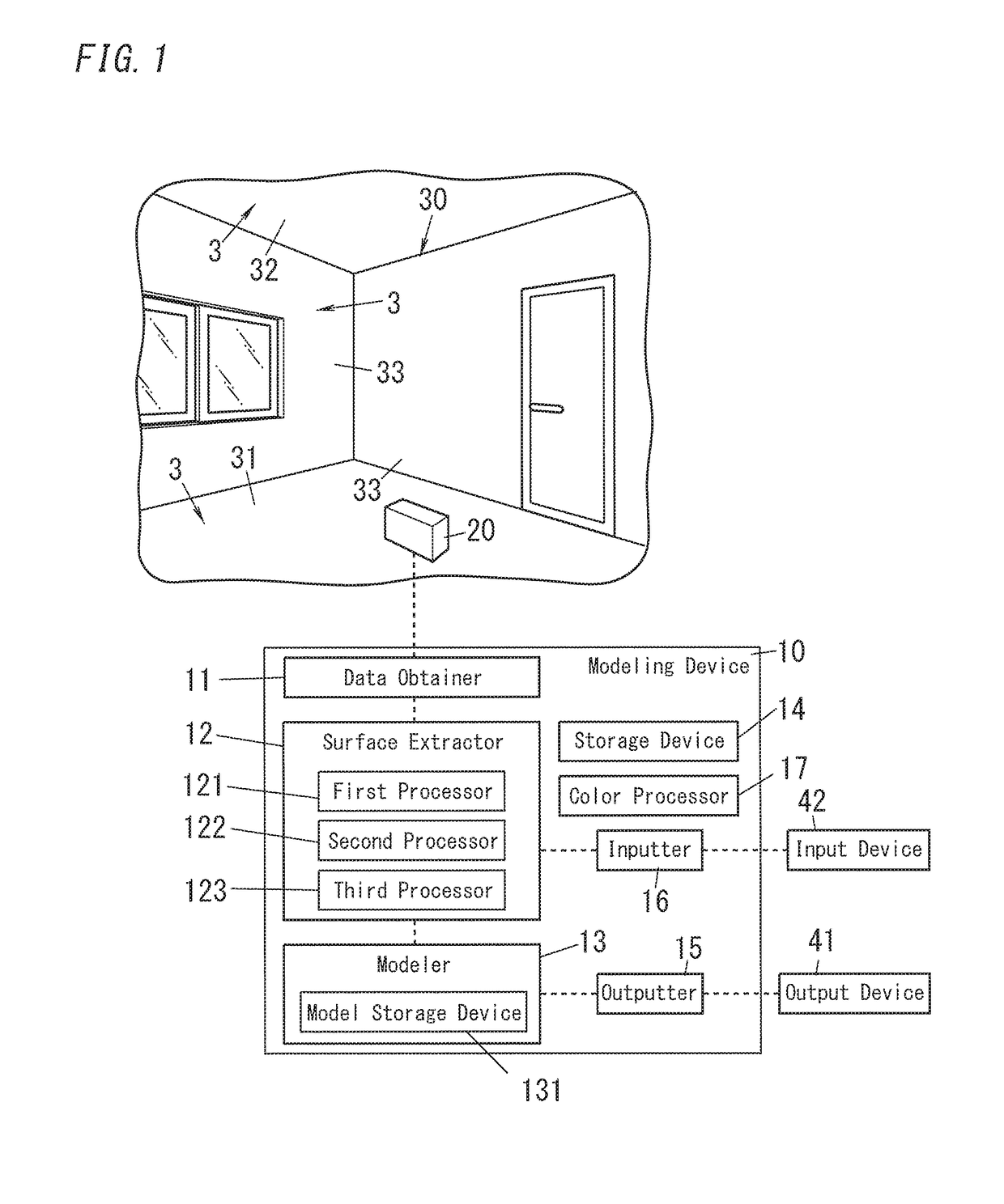
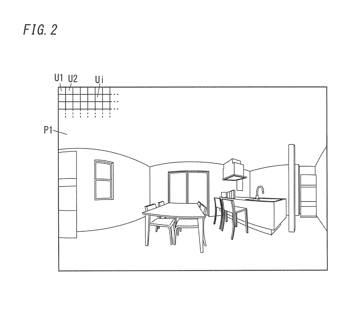
[0061]The first processor 121 divides a development image P1 as shown in FIG. 2 which is obtained by development of the three-dimensional object 30 on a plane. The development image has pixel values each of which includes a set of coordinates corresponding to the measurement data and also includes a grayscale value (preferably, a color value) of the image data of the three-dimensional object 30.
[0062]The first processor 121 divides the development image P1 into multiple unit regions Ui (i=1, 2, . . . ). Each unit region Ui may be set to have a size of 10 by 10 pixels. A small region including multiple pixels like a unit region Ui is referred to as a super pixel. It is sufficient that the number of pixels Qn (n=1, 2, . . . ) included in one unit region Ui is equal to or larger than four and is as large as to an extent that each of the surfaces 3 constituting the three-dimensional object 30 included in the development image P1 can be divided into multiple unit regions Ui. The unit reg...
operation example 2
[0098]In the aforementioned operation example, the unit regions Ui having the same direction are integrated into one surface region Sk. For example, when the wall surface 33 has steps, it is difficult to distinguish the unit regions Ui corresponding to the surfaces 3 which are parallel to each other but different from each other. For this reason, when the surface region Sk is formed by integrating the unit regions Ui based on information on the directions of the unit regions Ui only, there remains a probability that multiple surfaces 3 are integrated into one surface region Sk.
[0099]In such circumstances, the second processor 122 may preferably use additional information except for the information on the direction of the unit region Ui, together with this information. In more detail, as for candidates for the surface region Sk formed by classification based on the information on the directions of the unit regions Ui, the second processor 122 may preferably verify, by use of the addi...
operation example 3
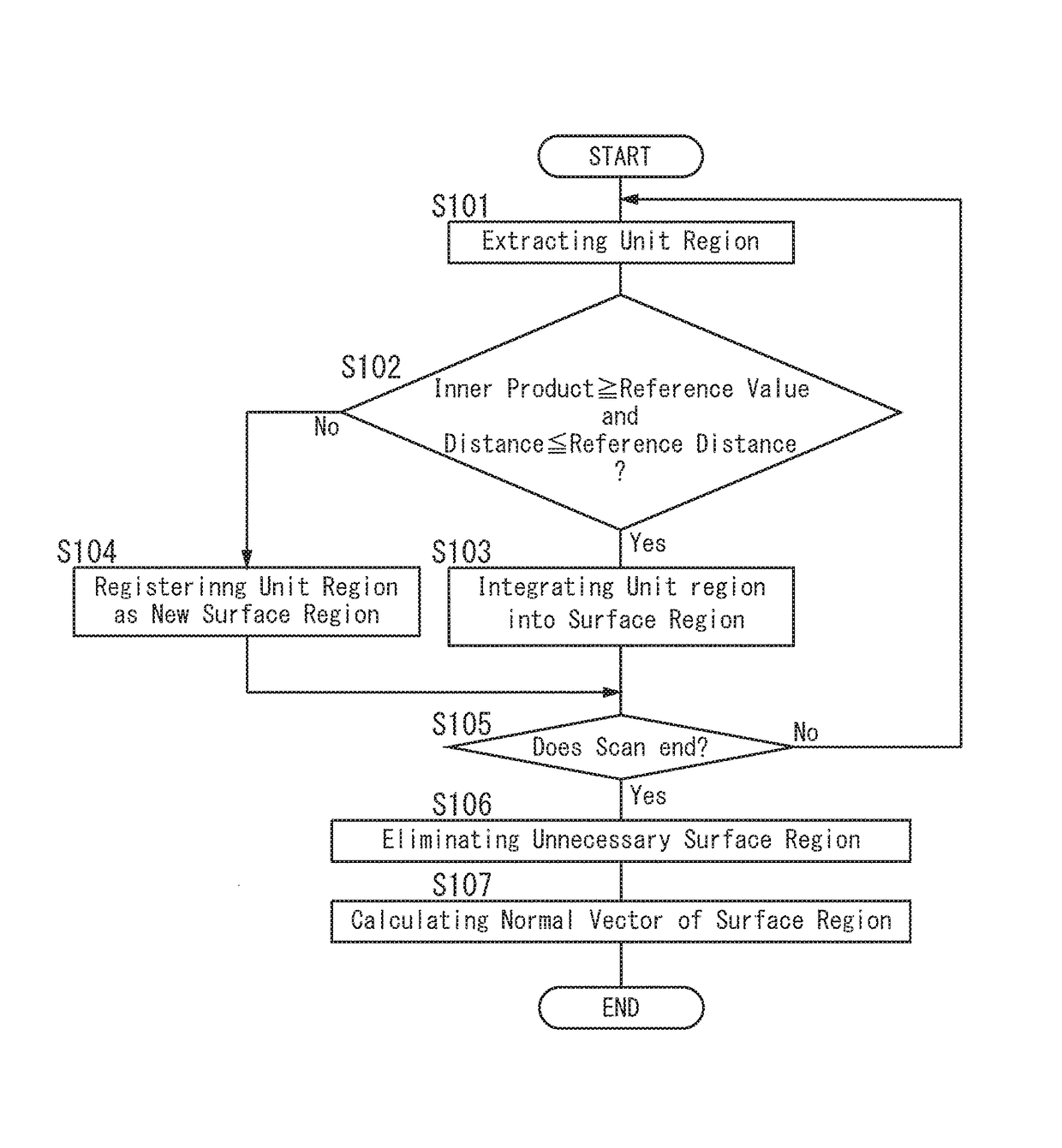
[0108]In the aforementioned operation example, the second processor 122 determines whether the unit region Ui which is given by the first processor 121 one by one belongs to any surface region Sk preliminarily added to the list. In summary, whether the unit region Ui is integrated into the surface region Sk is determined by use of the inner product of the normal vector Vi of the unit region Ui and the normal vector Tk of the surface region Sk on the list and the distance between the unit region Ui and the surface region Sk. By performing such a sequential process, the normal vector Tk of the surface region Sk may change as the unit region Ui is integrated into the surface region Sk, and this may cause deviation of the normal vector Tk from the original normal vector of the surface 3.
[0109]In view of this, after the surface region Sk is extracted by the process described in OPERATION EXAMPLE 1, the second processor 122 may preferably perform a process of redetermining whether the uni...
PUM
 Abstract
Description
Claims
Application Information
 - R&D
- Intellectual Property
- Life Sciences
- Materials
- Tech Scout
- Unparalleled Data Quality
- Higher Quality Content
- 60% Fewer Hallucinations
Browse by: Latest US Patents, China's latest patents, Technical Efficacy Thesaurus, Application Domain, Technology Topic, Popular Technical Reports.
© 2025 PatSnap. All rights reserved.Legal|Privacy policy|Modern Slavery Act Transparency Statement|Sitemap|About US| Contact US: help@patsnap.com