Supercharge Your Innovation With Domain-Expert AI Agents!

Constant velocity joint assembly

a constant velocity joint and assembly technology, applied in the direction of yielding couplings, clutches, rotary machine parts, etc., can solve the problems of assembly known in the art that does not provide robust venting and assembly known in the art can be damaged

Active Publication Date: 2019-01-22
DANA AUTOMOTIVE SYST GRP LLC
View PDF57 Cites 1 Cited by
  • Summary
  • Abstract
  • Description
  • Claims
  • Application Information

AI Technical Summary

Benefits of technology

The solution enables robust venting of pressurized gases and protects the constant velocity joint from damage by limiting the maximum articulation angle, ensuring the assembly's integrity and functionality.

Problems solved by technology

However, the assemblies known in the art do not provide robust venting.
Furthermore, the assemblies known in the art can be damaged when the assembly is taken beyond its maximum articulation angle.

Method used


Image

  • Constant velocity joint assembly
  • Constant velocity joint assembly
  • Constant velocity joint assembly

Examples


Embodiment Construction

[0021]It is to be understood that the invention may assume various alternative orientations and step sequences, except where expressly specified to the contrary. It is also to be understood that the specific devices and processes illustrated in the attached drawings, and described in the following specification are simply exemplary embodiments of the inventive concepts defined herein. Hence, specific dimensions, directions or other physical characteristics relating to the embodiments disclosed are not to be considered as limiting, unless expressly stated otherwise. Also, although they may not be, like elements in various embodiments may be commonly referred to with like reference numerals within this section of the application.

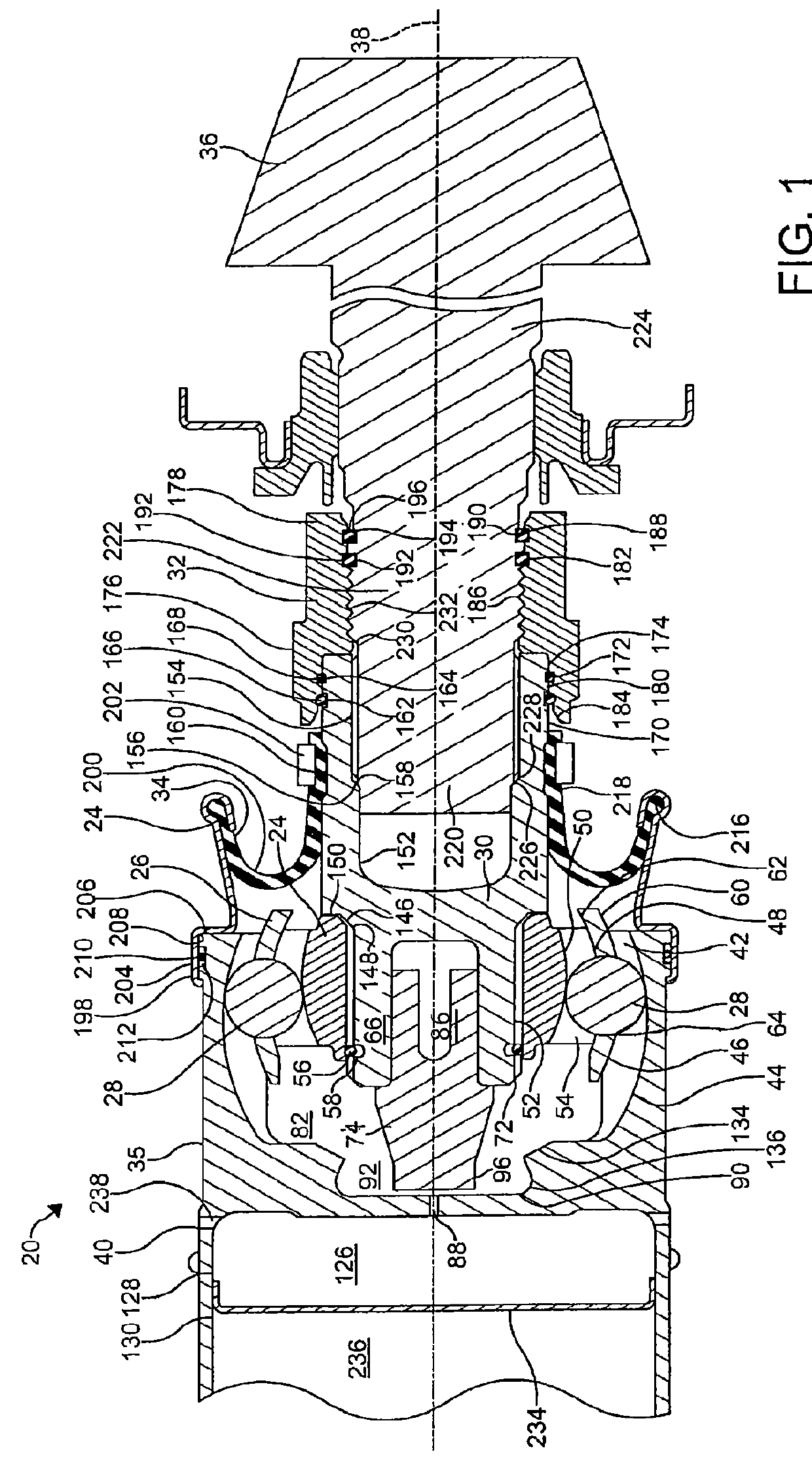
[0022]A constant velocity joint assembly 20, 20A, 20B, 20C, 20D will be described herein. The constant velocity joint assembly 20, 20A, 20B, 20C, 20D will be described in connection with a vehicle (not depicted). However, it would be understood by one of ordin...


PUM


Abstract

A constant velocity joint assembly (20) includes an outer race (22) having a plurality of outer tracks (42) formed in an inner surface thereof and an inner race having a plurality of inner tracks (54) formed in an outer surface thereof. A cage (26) is disposed between the inner race and the outer race. A plurality of torque transferring elements (28) are disposed in the cage. Each torque transferring element contacts one of the outer tracks of the plurality of outer tracks and one of the inner tracks of the plurality of inner tracks. A drive sleeve (30) is separated from the plurality of torque transferring elements by the inner race. Also, the drive sleeve is in driving engagement with the inner race. A stopper portion (74) is attached to the drive sleeve. The stopper portion comprising a portion that reduces in thickness toward an outer end thereof.

Description

CROSS-REFERENCE TO RELATED APPLICATION[0001]This application is claiming the benefit, under 35 U.S.C. 119(e), of the provisional application which was granted Ser. No. 61 / 975,130 and filed on Apr. 4, 2014, the entire disclosure of which is hereby incorporated by reference.BACKGROUND OF THE INVENTION[0002]The invention relates to a constant velocity joint assembly which facilitates venting pressurized gases in the assembly to the atmosphere. More specifically, the invention relates to a direct pinion mount constant velocity joint assembly which facilitates venting pressurized gases in the assembly to the atmosphere and prevents damage to the assembly by limiting the maximum articulation angle.[0003]Constant velocity joint assemblies are known. However, the assemblies known in the art do not provide robust venting. Furthermore, the assemblies known in the art can be damaged when the assembly is taken beyond its maximum articulation angle. Therefore, it is desired to provide an improve...

Claims


Application Information

Patent Timeline
Patent Type & Authority Patents(United States)
IPC IPC(8): F16D3/24F16D3/224F16D3/223
CPCF16D3/224F16D3/223F16D2003/22313Y10S464/906F16D2003/2232Y10T464/10F16D2300/0212F16D3/845
Inventor OH, SEUNG TARKTAVARES, DILSON DA SILVEIRA
Owner DANA AUTOMOTIVE SYST GRP LLC
Features
  • R&D
  • Intellectual Property
  • Life Sciences
  • Materials
  • Tech Scout
  • Unparalleled Data Quality
  • Higher Quality Content
  • 60% Fewer Hallucinations
Learn More