Supercharge Your Innovation With Domain-Expert AI Agents!

Sheet feeding apparatus and image forming apparatus

a technology of feeding apparatus and sheet, applied in the field of sheet feeding apparatus, can solve problems such as unfavorable situations, and achieve the effect of preventing multiple feeding of sheets and stable sheet conveyan

Active Publication Date: 2019-02-26
CANON KK
View PDF10 Cites 0 Cited by
  • Summary
  • Abstract
  • Description
  • Claims
  • Application Information

AI Technical Summary

Benefits of technology

This approach prevents multiple sheet feeding and enhances the stability of sheet conveyance by ensuring the pickup member only engages with the intended sheet, reducing the likelihood of sheet jams and improving overall printing efficiency.

Problems solved by technology

However, in the course of improving stability of conveyance of sheets by carrying out pickup operations multiple times by the pickup member, there were cases where a sheet stacked below the uppermost sheet being fed, hereinafter referred to as a succeeding sheet, is picked up undesirably by the pickup member.
The succeeding sheet is fed from the sheet supporting portion along with the feeding of the uppermost sheet, thereby causing undesirable situations such as occurrence of multiple feeding of sheets.

Method used


Image

  • Sheet feeding apparatus and image forming apparatus
  • Sheet feeding apparatus and image forming apparatus
  • Sheet feeding apparatus and image forming apparatus

Examples


first embodiment

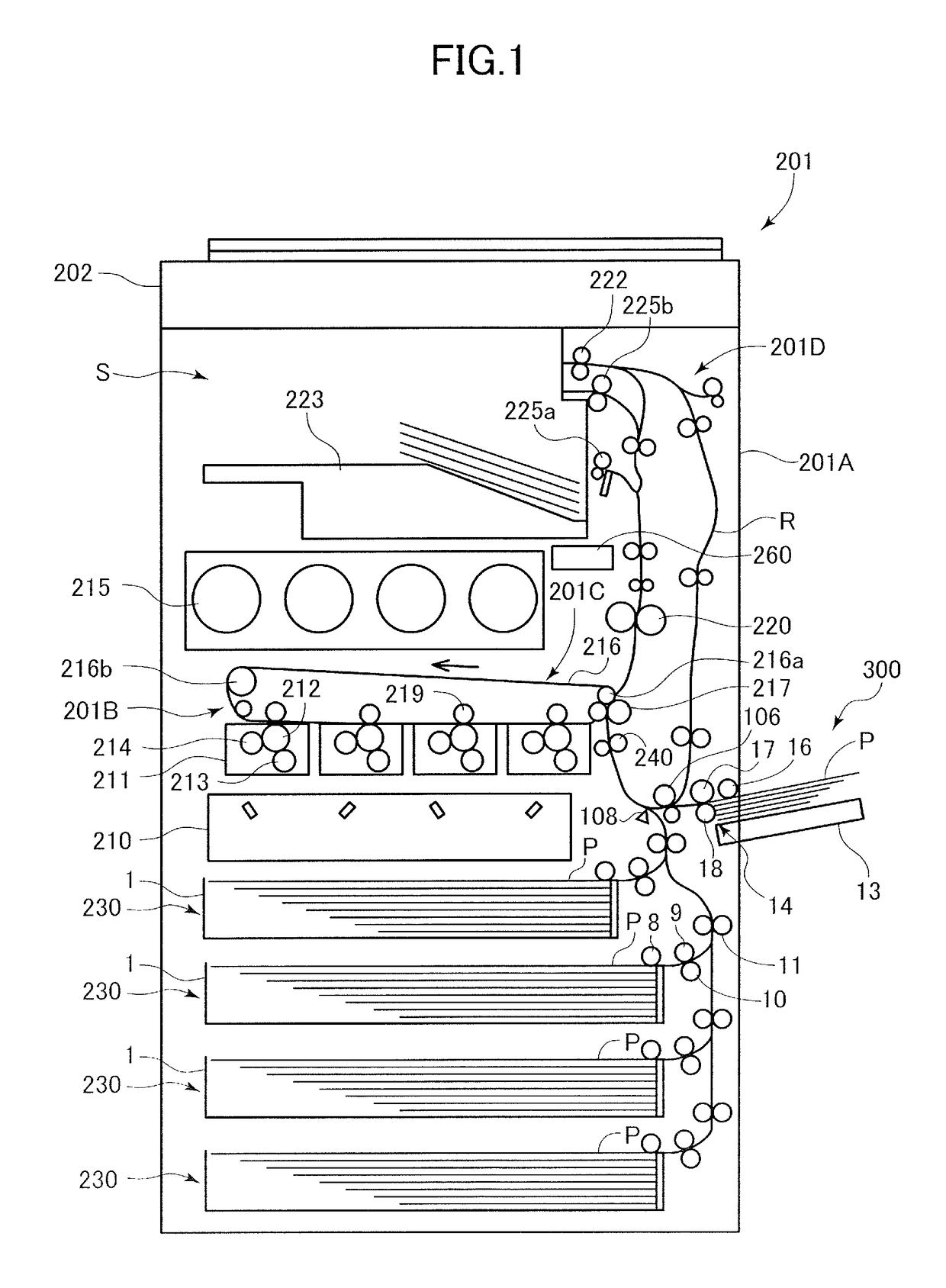
[0036]As illustrated in FIG. 1, a sheet feeding apparatus according to a first embodiment is provided as a portion of a full-color laser beam printer 201, hereinafter referred to as printer, serving as an example of an image forming apparatus. The printer 201 includes a printer body 201A serving as an image forming apparatus body, an image forming portion 201B configured to form an image on a sheet, and an image reading apparatus 202 disposed substantially horizontally on an upper portion of the printer body 201A. The printer 201 is a so-called in-body sheet discharge-type image forming apparatus in which a sheet discharge space S into which sheets are discharged is formed between the image reading apparatus 202 and the printer body 201A.

[0037]A plurality of sheet feeders 230 are provided in a lower portion of the printer body 201A, and are each equipped with a sheet feed cassette 1 serving as a sheet storage portion capable of storing sheets P. Each sheet feeder 230 is equipped wit...

second embodiment

[0108]Next, a configuration of a manual sheet feeder serving as a sheet feeding apparatus according to a second embodiment will be described. The manual sheet feeder according to the present embodiment differs from the first embodiment in conditions for executing double-rotation feeding, and other configurations are the same as the first embodiment. Therefore, elements that are common to the first embodiment are denoted with the same reference numbers as the first embodiment, and descriptions thereof are omitted.

[0109]As illustrated in FIG. 14, according to the present embodiment, double-rotation feeding is executed if the following conditional expression (4) is satisfied in addition to the condition expressions (1) through (3) of the first embodiment.

Feed Time(T)>Fixed Threshold(Tc)  (4)

[0110]The fixed threshold Tc is a reference time set in advance, and represents a lower limit of feed time T based on which double-rotation feeding can be executed. It is considered that if the feed...


PUM


Abstract

A sheet feed portion feeds a sheet by performing a pickup operation in a cycle in which a pickup rotary member is switched from a released state to a contact state and then switched to the released state. A detection unit detects the sheet at a position downstream of the sheet feed portion in the sheet feeding direction. A control unit is capable of executing a first feed mode in which a first feed process of carrying out a pickup operation is executed, or a second feed mode in which the first feed process is executed and then a second feed process of carrying out an additional pickup operation is executed. The mode to be executed is determined based on a time when the sheet is detected by the detection unit and a length of the sheet.

Description

BACKGROUND OF THE INVENTION[0001]Field of the Invention[0002]The present invention relates to sheet feeding apparatuses configured to feed sheets to apparatuses such as image forming apparatuses and to image forming apparatuses.[0003]Description of the Related Art[0004]Sheet feeding apparatuses adopted in image forming apparatuses such as printers, copying machines or facsimiles are usually equipped with a pickup member to pick up sheets supported on a sheet supporting portion, and a conveyance member to receive and convey the sheets fed by the pickup member. Further, some sheet feeding apparatuses adopt a configuration in which a pickup member is relatively moved with respect to the sheets along with the driving of the pickup member, so that the pickup member picks up the sheets one by one by performing a pickup operation in which the pickup member comes in contact with the sheet supported on the sheet supporting portion, and then the contact state is released.[0005]Japanese Unexam...

Claims


Application Information

Patent Timeline
Patent Type & Authority Patents(United States)
IPC IPC(8): B65H1/14G03G15/00B65H7/02B65H7/20B65H3/06
CPCB65H1/14B65H3/0607B65H7/20B65H3/0684B65H7/02G03G15/6514B65H2511/414B65H2511/13B65H2407/21B65H2511/11B65H2220/01B65H2220/02G03G15/6511G03G15/6538
Inventor SAKURAI, YUTA
Owner CANON KK
Features
  • R&D
  • Intellectual Property
  • Life Sciences
  • Materials
  • Tech Scout
  • Unparalleled Data Quality
  • Higher Quality Content
  • 60% Fewer Hallucinations
Learn More